You must be signed in to read the rest of this article.
Registration on CDEWorld is free. Sign up today!
Forgot your password? Click Here!
Expansive techniques (split crest, edentulous ridge expansion [ERE], ridge expansion osteotomy [REO]) can be used in Class IV premaxilla and posterior mandibular levels.1-6 These techniques use bone elasticity and plasticity to widen, by means of intracortical osteotomy of the alveolar crest, the spongious space between the atrophic crest. In fact, osteotomies incise the residual alveolar crest longitudinally with a transversal widening, which simultaneously creates an adequate socket for the implants. After the implants have been placed, they immediately act as space retainers, keeping the two cortical walls apart.
Surgical expansive techniques developed as a consequence of the observation that maxillary bones have extremely predictable resorption patterns. From Atwood’s7 analysis and Cawood and Howell’s8 clinical classification, it appears that resorption vectors are different according to the site; moreover, the final result of the atrophic process is an apparent contraction of the upper jaw centripetally while the mandible contracts centrifugally. Edentulism causes various anatomo-morphologic microscopic alterations: a different spatial disposition of the osseous trabecula9 and an endoperiosteal corticalization of the endoperiosteal spaces occur.10 The vascular supply to the maxillary bone changes, reducing the endosseous flow and increasing the extraperiosteal one. Specifically, edentulous maxillary bone undergoes a progressive volumetric reduction and centripetal contraction of the arch. The outcome of this process consists of Type IV atrophic bone with a knife-edged anterior crest, with an adequate cortical height and an inadequate spongious thickness.8
The first surgical technique was proposed in 1985 by Osborn, who described an extensive alveoloplasty with simultaneous hydroxyapatite crystal grafting to improve long-term stability of full-arch removable denture prostheses.5,6 Tatum was the first to propose, in 1986, an osteotome technique for endosseous implant positioning by means of progressive compaction and simultaneous dislocation of the vestibular cortical wall of the upper maxilla.11 Since then, many expansion surgical techniques have been described and various osteotome surgical kits are available to perform different surgical procedures, such as alveolar remodeling, slight osteotomic sinus lifting, and immediate postextractive implant positioning.12-18 Most surgical osteotome kits provide concave osteotomes that need to be pushed through the maxillary bone by means of a hammer, causing apical bone compression.
The development of the alternating osteotome with variable conicity technique represents an attempt to increase implant success rates in atrophic maxillae. This method of manual osteotomic preparation of implant sites involves a system based on two kinds of working spikes that cause two vectorial forces of compression apically and surrounding the implant site preparation. This article describes this technique and demonstrates its use in three clinical applications.
METHODS AND MATERIALS
Building Characteristics and Surgical Technique
The alternating osteotome with variable conicity technique uses a surgical kit (Bontempi Medizintechnik GmbH, www.bontempi-chirurgie.de) consisting of 11 devices: eight troncoconical osteotomes, numbered 1 to 8; and three corrective osteotomes, one for 5-mm diameter implants and two for cylindrical implants. These osteotomes are between 4 mm and 13 mm in length, with a difference of 1.5 mm from one device to the next. The troncoconical osteotomes have alternating concave and convex spikes of 2.5 mm in diameter, with different functions (Table 1). The spikes and working bases have a constant diameter, while the difference between the devices lay in their lengths. The various lengths cause a progressive conicity of the osteotomes, with each device having greater conicity than the previous one in the sequence (Figure 1A through Figure 1C).
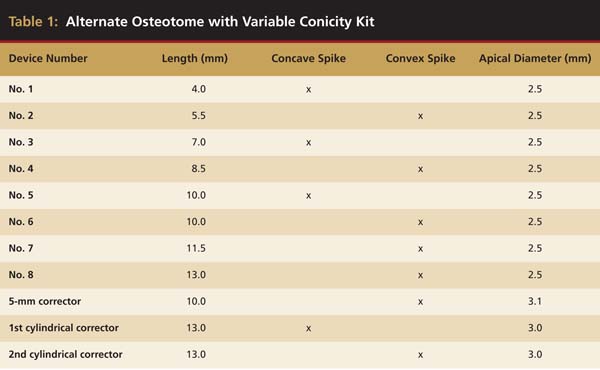 |
 Figure 1A through Figure 1C Alternating concave/convex spikes in progressive lengths. |
The conicity grade for all the osteotomes corresponds to the one of the kernel (ie, implant body without anfractuosities) of a classic troncoconical implant. Therefore, this osteotome system should be used when troncoconical and cylindrical implants (8.5 mm to 13 mm in length, with 4.1 mm to 5 mm in diameter) will be placed.
Alveolar Remodeling
The thickness of the atrophic crest is the determining factor when choosing the surgical approach in the upper jaw. The split crest is the standard technique for the atrophic crest up to 4 mm. Beyond this limit, the alternating osteotome with variable conicity technique represents a reliable surgical option.19 The first bur (2 mm in diameter) needs at least 1 mm of vestibular and palatal bone, therefore the minimal thickness required for use of this technique is 4 mm.
The following is the operative sequence:
1. A rose-headed bur (2 mm in diameter) is used to create a generous pathway for the first osteotome.
2. A preparation bur (2 mm in diameter) is used up to its working-range limit. If there is a particularly rigid cortical part in the anterior sectors, an additional preparation bur (2.5 mm in diameter) can be used.
3. If there is an hourglass-shaped crest with clear vestibular resorption, a progressive axial correction can be performed.
a. A 5-mm long preparation bur (2 mm in diameter) is used, slightly inclined to the palate.
b. A No. 4 osteotome is employed to create the osteotomy.
c. A preparation bur at working-range limit is used, more inclined to the palate.
4. Alternating concave and convex osteotomes are used to create the osteotomies until the pre-elaborated bur working range is achieved.
This operative sequence allows progressive ascension of the osteotomy and creates anatomic modeling of the neoalveolus. Furthermore, because the alveolar vestibular portion is collapsed and the interproximal portion compressed, radicular draft and new alveolar apexes are obtained and are fundamental for the new papillae regeneration.19 The final morphology, therefore, is similar to the natural alveolar anatomy because of the creation of a crenate contour of the crestal bone.
Case 1
A 45-year-old female was referred for implant placement and prosthetic treatment in the area of tooth No. 24. The tooth had been extracted 4 years prior; the patient did not wear any denture thereafter. The radiograph revealed adequate bone height and a 5-mm to 6-mm ridge at the crest (Figure 2). It was decided to place a 11.5 mm in length, 3.75 mm in diameter Tapered Screw-Vent® implant (Zimmer Dental, www.zimmerdental.com) using the alveolar remodeling technique in the area of tooth No. 24.
At the time of surgery, local infiltrative anesthesia was administered (lidocaine 2% with epinephrine, 1:100,000). A full-thickness mucoperiosteal flap was raised. The initial osteotomy was performed on midcrestal bone using a rose-headed bur. To prepare the osteotomy site for implant placement, sequential alternating osteotomes with variable conicity were used, drilling 2-mm shorter than the length of the implant to be placed (Figure 3A and Figure 3B). The implants presented initial primary stability (Figure 4), the cover screws were placed, and the implants were submerged for a healing period. The tissue was approximated, and the patient was instructed not to wear any denture or to place pressure on the healing site.
Second-stage surgery was performed after 5 months; healing abutments were placed, and the soft tissue was allowed to heal for an additional 5 weeks. Splinted porcelain-fused-to-metal (PFM) crowns supported by custom gold abutments then were delivered (Figure 5).
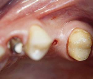 Figure 2 Preoperative view of the area around tooth No. 24. On the left, a previously placed implant abutment is visible. | 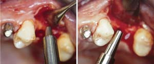 Figure 3A and Figure 3B Alternating osteotomes with variable conicity used to perform the alveolar remodeling in the area of tooth No. 24. |
 Figure 4 Implant positioning; the radiograph taken 4 weeks after placement confirmed good primary stability. | 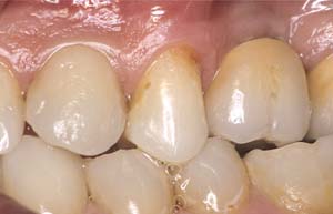 Figure 5 Final implant-supported PFM restorations. |
Slight Osteotomic Maxillary Sinus Lifting
Using the alternating osteotome with variable conicity technique for slight osteotomic maxillary sinus lifting allows the apical placement of the Schneiderian membrane, by compressing and dislocating with specific cylindrical osteotomes in a progressive and atraumatic manner, the spongiosa of the remaining alveolar process farther than the maxillary sinus wall.
The alternating osteotome technique is indicated in the upper maxillary lateral sectors, where bone Type III and Type IV prevail.16,20 In types III and IV bone, the osteotomes provoke a dislocation compression of the spongious bone toward the sides and upward. At the end of the procedure, a corticalized osseous margin surrounding the implant neosite is obtained.
Crestal access to the maxillary sinus allows the positioning of fixtures in the sinus site by invading it for a few millimeters.2,21 The following is the operative sequence of the alternating osteotome technique:
1. A rose-headed bur (2 mm in diameter) is used to prepare the cortical bone.
2. The concave osteotome (4 mm in diameter) is inserted into the prepared site. The osteotome deepens passively for 2 mm and then dislocates another 2 mm, achieving a depth of 4 mm. The dislocation level is conditioned by the pre-elaborated device morphology provided by a cortical stop. The osteotomic dislocation occurs mainly with the bone compressed apically.
3. The 4-mm convex osteocompressor is inserted passively to dislocate 1.5 mm of bone; the depth is established by a firm cortical block.
4. The same procedure is performed with the 5.5-mm concave osteotome passively positioned to dislocate 1.5 mm of bone. The dislocation forces mainly are concentrated vertically.
5. This same procedure is performed with the 8.5-mm convex osteocompressor, with the first 7 mm positioned passively to dislocate 1.5 mm of bone. After achieving this step, it is possible to insert, if treatment planned, a 4.1 mm x 8.5 mm conical implant.
6. The same procedure is performed with the 10-mm concave osteotome, with the first 8.5 mm inserted passively to dislocate the next 1.5 mm of bone.
7. The same technique is performed with the 10-mm convex osteocompressor. Compared with the previous device, this compressor further lifts the maxillary sinus wall and allows an apical refining that can permit insertion of a 4.1 mm x 10 mm conical implant.
8. The same procedure is performed with the 11.5-mm convex osteocompressor. After this step, it is possible to insert, if treatment planned, a 4.1 mm x 11.5 mm conical implant.
9. The same procedure is performed with the 13-mm convex osteocompressor. Then, it is possible to insert, if treatment planned, a 4.1 mm x 13 mm conical implant.
After step 5, if the insertion of a 5-mm diameter implant is intended, the sequence can be concluded with the desired osteocompressor and 5-mm implant corrector. Similarly, if a cylindrical implant is wished, the sequence can be concluded with the properly sized osteocompressor, followed by the two cylindrical implant correctors: concave and convex. Furthermore, during this sequence, after the sinus cortical bone depth is reached, the microfilling step can be executed with microfragments of heterologous bone, filling the neoalveolus and then repeating the osteotomic sequence. Thereafter, to increase the osteotomic lifting entity, the newly formed alveolar cavity is filled and the sequence repeated until the use of the last osteotome corresponds to the chosen implant. This technique permits adequate osteotomic lifting of the sinus membrane without tearing it. Moreover, because of the eventual filling of the implant site, it allows fine modeling of the forces used to lead the devices into the sinus floor bone.19
Case 2
A 55-year-old male was referred for implant placement and prosthetic rehabilitation in the area of tooth No. 15. The tooth had been extracted 4 years prior. The radiograph revealed inadequate bone height for implant positioning (Figure 6). It was decided to insert an implant that was 11.5 mm in length and 3.75 mm in diameter, performing a slight osteotomic maxillary sinus lift. A heterologous bone graft also was planned to obtain a larger sinus lift.
A full-thickness mucoperiosteal flap was raised, and alternating osteotomes were used to prepare the implant site. After achieving a length of 7 mm (Figure 7A and Figure 7B), heterologous bone graft was implanted and the osteotome sequence was repeated. The implant showed primary stability.
Second-stage surgery was performed after 4 months (Figure 8); healing abutments were placed and the soft tissue was allowed to heal for 5 more weeks. Then, splinted porcelain-fused-metal (PFM) crowns supported by custom gold abutments were delivered (Figure 9 and Figure 10).
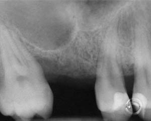 Figure 6 Preoperative radiograph of the area around tooth No. 15. | 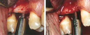 Figure 7A and Figure 7B Alternating osteotomes with variable conicity used to perform the alveolar remodeling in the area of tooth No. 15. |
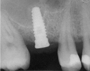 Figure 8 At 4 months after treatment, the radiograph revealed the presence of a bone layer surrounding the implant. | 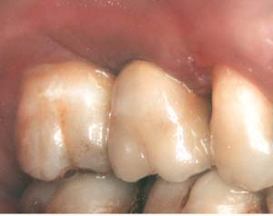 Figure 9 Final implant-supported PFM restorations. |
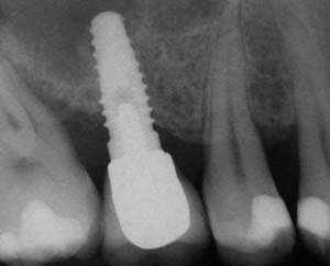 Figure 10 Posttreatment radiograph, after cementation of the final restorations. |
Immediate Postextractive Implant Positioning
Tooth extraction, because of radicular fractures, endodontic failures, radicular decays, or periodontal disease, must be performed with a flapless technique. Syndesmotomies after rhizotomy can be used to preserve the alveolar bone.22
The implant site preparation needs to be planned more palatally than the root position. This positioning is important because the spongious bone will be dislocated apicocoronally in the vestibular region. The osteotome will lean on the most rigid palatal part and will act in low-resistant sites, ie, toward the thinnest vestibular fraction of cortical bone. The result is a compression of the medullar part vestibularly, thus filling the space left by the extracted radix, increasing the osseous density and generating a natural filling of the alveolar site’s vestibular component.
The main difference between the implant site preparation with burs and the one performed using the alternating osteotome technique is that in the former, the osseous tissue close to the implant is damaged by cutting and high-speed bur microtrituration.19 In the latter, the tissue remains vascularized because it is subjected to dislocation and compression only. Even if the action of the osteotome reduces the number and size of the spongious collagenic lacunae, it increases lacunae density, which is desirable for immediate implant loading.19
The operative sequence (Figure 11) is as follows:
1. A pilot drill (2 mm in diameter) is used to create a pilot hole to the length of the implant that is planned to be inserted.
2. A single convex osteotome with the same length and diameter of planned implant is used to create the osteotomy.
3. If a cylindrical implant is planned, the cylindrical corrector should be used.
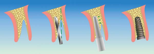 Figure 11 Surgical procedure of immediate postextractive implant positioning by means of alternating concave osteotomes. |
Case 3
A 53-year-old female was referred for evaluation of a fracture of tooth No. 24. The tooth had been treated endodontically 5 years prior. The radiograph revealed a complete fracture of the tooth involving the crown (Figure 12). Tooth extraction and immediate placement of a an implant that was 10 mm in length and 3.75 in diameter was planned.
At the time of surgery, the tooth was extracted without harvesting any mucosal flap because the implant site was prepared by means of a pilot drill bur (Figure 13) and alternating osteotomes (Figure 14A and Figure 14B). The implant was positioned and showed primary stability. The implant was loaded 2 days after surgery. Then, splinted PFM crowns supported by custom gold abutments were delivered. At 6 months posttreatment, the radiograph revealed no bone resorption and the clinical result was optimal (Figure 15A and Figure 15B).
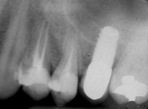 Figure 12 Preoperative radiograph shows fractured tooth No. 24. | 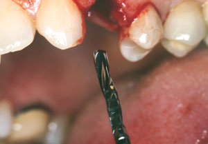 Figure 13 The drill bur was used to start the implant site preparation. |
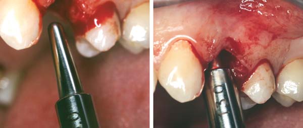 Figure 14A and Figure 14B Alternating osteotomes were used to prepare the implant site. |
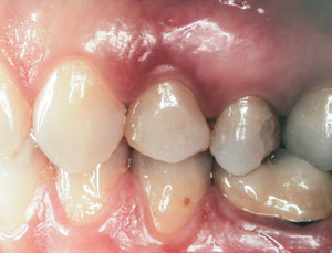 Figure 15 A Final implant-supported PFM restorations. | 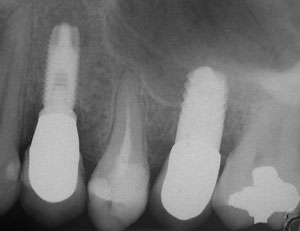 Figure 15B Posttreatment radiograph, 6 months after the initial surgery. |
DISCUSSION
The alternating osteotome with variable conicity technique was developed after an analysis of the implant positioning risk factors in atrophic maxillae, which often are deficient in bone quality and quantity.
Poor bone quality has negative effects on implant success rates.23 Another negative factor influencing implant success rates is implant length. Threaded titanium implants have a high failure rate associated with poor bone quality; and moreover, significant discrepancies in long-term implant survival rates have been reported in different implant lengths for titanium plasma-sprayed and hydroxyapatite implants.19,24
The alternating osteotome with variable conicity system has been designed for use when low quality and low quantity of bone exists. The convex osteocompressor can work with low-quality bone, and the concave osteotomes can work with the low quantity of bone, allowing implant placement in poor-quality bone with reduced thickness.
All osteotomes present a wide stop at the basis of the working spike, which is connected by a rounded curve. Such structural characteristics allow the osteotome to compress the cortical bone, minimizing the risk of fracture, achieving a progressive dilatation. Additionally, the device can be inserted easily.
Progressive conicity allows an easy osteotome insertion in sequence: each osteotome is inserted passively through a path corresponding to the osteotomy created by the previous device and continues the osteotomic action for only 1.5 mm, ie, the length difference between an osteotome and the subsequent one.
The conical conformation, alternation of apical concavity and convexity, wide stop, and well-represented handle avoid the use of the hammer percussively, except for rare cases.19 It is sufficient to rotate the device clockwise with a slight push to allow the latter to go deeper until reaching the mechanical stop. Such a mechanical stop is, as a result, extremely useful for compression and dislocation vestibularly of the vestibular cortical bone. Moreover, the pre-elaborated cortical stop of the osteotomes empowers the surgeon to gradually increase the depth of the implant site, thus reducing the perforation hazard.19
Osteotomes have two types of working extremities: concave and convex. The concave spike mainly cuts, while the convex one deals with compression. The alternating use of concave osteotomes and convex osteocompressors allows two different vectors of osteocompression. The first is directed apically, while the second is directed lengthwise. The concave osteotomes are sharp at the apex and transmit their dislocating force vertically. The convex osteocompressors laterally disperse the forces that tend to create resistance at the apex.
During the intermediate preparatory phase of the site, it is advisable to increase the resistance level through the positioning of grafting material, such as heterologous deproteinized bone.22 A greater amount of grafting material is necessary in case of low-density bone and severe atrophy.
However, it is necessary to establish the differences between the Summers’ technique and the alternating osteotome with variable conicity technique. The two main differences are that the use of concave and convex osteocompressors allows firm bone compaction apically and along the full length of the implant site and that these two forces reduce the perforation hazard by allowing the surgeon to increase gradually the depth of the preparation, thus reducing the trauma generated by device progression through the bone.19
The various clinical applications of this osteotome system make it useful in many indications as a complementary element to the use of rotating devices. Furthermore, using the system can reduce one of the main osteotome technique drawbacks—the psychologic and physical discomfort of the patient induced by hammer percussion.
CONCLUSION
The use of the alternating osteotome with variable conicity technique could be considered an extremely wide-ranging complement to the traditional technique of implant site preparation with rotating devices. The use of alternating instrumentation during site preparation can compact and vertically move the bone where a volumetric reduction in these directions has occurred. When unexpected bone deficiency with vestibular collapse occurs, the use of these osteotomes can restore the emerging profile of the future prosthetic manufactured product, through cortical transversal widening and spongious bone compacting.
The use of surfaces constantly eases the bone–implant contact, which, in many cases, required major surgery with the traditional osteotome technique. The sum of implant evolution, the knowledge related to the suitable morphology, and structural emancipation of the surfaces has delocalized the “borderline case concept,” converting some cases from soluble only with maxillary sinus lifting or autologous bone grafting to cases soluble with osteotomic surgery associated with the recent generation of implants.
As described, the ductility related to the various indications and the low trauma give this system added value. The alternating osteotome with variable conicity technique should be considered routinely during the surgical planning of clinical cases of upper jaw atrophy.
DISCLOSURE
The surgical technique presented in this article was designed by Dr. Malchiodi. The surgical kit is distributed by Bontempi, from which the inventor has not received any financial remuneration.
REFERENCES
1. Summers RB. A new concept in maxillary implant surgery: the osteotome technique. Compend Contin Educ Dent. 1994;15(2):152-160.
2. Summers RB. The osteotome technique: part 3—less invasive methods of elevating the sinus floor. Compend Contin Educ Dent. 1994;15(6):698-710.
3. Summers RB. The osteotome technique: part 4—future site development. Compend Contin Educ Dent. 1995;16(11):1090-1099.
4. Summers RB. The osteotome technique: part 2—the ridge expansion ostetomy (REO) procedure. Compend Contin Educ Dent. 1994;15(4):422-436.
5. Osborn JF. Extension alveoloplasty (I). New surgical procedures for the treatment of alveolar collapse and residual alveolar ridge atrophy [in German]. Quintessenz. 1985;36(1):9-16.
6. Osborn JF. Extension alveoloplasty (II). New surgical procedures for the treatment of alveolar collapse and residual alveolar ridge atrophy [in German]. Quintessenz. 1985;36(2):239-246.
7. Atwood DA. Some clinical factors related to the rate of resorption of residual ridge. J Prosthet Dent. 1962;12:441-459.
8. Cawood JI, Howell RA. A classification of the edentulous jaws. Int J Oral Maxillofac Surg. 1988;17(4):232-236.
9. Ulm C, Solar P, Blahour R, et al. Reduction of the compact and cancellous bone substances of the edentulous mandible caused by resorption. Oral Surg Oral Med Oral Pathol. 1992;74(2):131-136.
10. Carter DR. Mechanical loading histories and cortical bone remodelling. Calcif Tissue Int. 1984;36(suppl 1):1547-1551.
11. Tatum H Jr. Maxillary and sinus implant reconstructions. Dent Clin North Am. 1986;30(2):207-229.
12. Bryant SR. The effects of age, jaw site, and bone conditions on oral implant outcomes. Int J Prosthodont. 1998;11(5):470-490.
13. Hutton JE, Heath MR, Chai JY, et al. Factors related to success and failure rates at 3-year follow-up in a multicenter study of overdentures supported by Brånemark implants. Int J Oral Maxillofac Implants. 1995;10(1):33-42.
14. Khang W, Feldman S, Hawley CE, et al. A multi-center study comparing dual acid-etched and machined-surface implants in various bone qualities. J Periodontol. 2001;72(10):1384-1390.
15. Sennerby L, Roos J. Surgical determinants of clinical success of osseointegrated oral implants: a review of the literature. Int J Prosthodont. 1998;11(5):408-420.
16. Lekholm U, Zarb GA. Patient selection and preparation In: Brånemark P-I, Zarb GA, Albrektsson T, eds. Tissue-Integrated Prostheses: Osseointegration in Clinical Dentistry. Chicago, IL: Quintessence Publishing Co; 1985:199-209.
17. Higuchi KW, Folmer T, Kultje C. Implant survival rates in partially edentulous patients: A 3 year prospective multicenter study. J Oral Maxillofac Surg. 1995:53(3):264-268.
18. Bergendal T, Engquist B. Implant-supported overdentures: a longitudinal prospective study. Int J Oral Maxillofac Implants. 1998;13(2):253-262.
19. Malchiodi L. Anatomia e chirurgia dei seni mascellari. In: Malchiodi L, ed. Chirurgia Implantare. Bologna, Italy: Edizioni Martina; 2003:219-225.
20. Esposito M, Hirsch JM, Lekholm U, et al. Biological factors contributing to failures of osseointegrated oral implants. (I). success criteria and epidemiology. Eur J Oral Sci. 1998;106(1):527-551.
21. ten Bernard JP, Belser U, Szmuckler S, et al. 3-years success rate of short ITI implants in posterior jaws. Med Buccale Chir Buccale. 1995;1:11-18.
22. Zeren KJ. Minimally invasive extraction and immediate implant placement: the preservation of esthetics. Int J Periodontics Restorative Dent. 2006;26(2):171-181.
23. Bruggenkate CM, Asikainen P, Foitzik C, et al. Short (6-mm) nonsubmerged dental implants: results of a multicenter clinical trial of 1 to 7 years. Int J Oral Maxillofac Implants. 1998;13(6):791-798.
24. Lum LB. A biomechanical rationale for the use of short implants. J Oral Implantol. 1991;17(2):126-131.


