You must be signed in to read the rest of this article.
Registration on CDEWorld is free. Sign up today!
Forgot your password? Click Here!
CBCT and Optical Scan Integration
Cone beam computed tomography (CBCT) data is often referred to as a “virtual patient” because of its ability to capture an exact 3-dimensional (3-D) representation of the patient’s anatomy.1,2 This digital data is very powerful on its own for both diagnostic and treatment-planning purposes and, because of these benefits, there has been tremendous growth in its acceptance and utilization in dentistry.
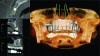
However, this potential is only a starting point. On account of CBCT’s unique characteristics of being a real-size 3-D image, it can also act as the matrix for other digital information to be integrated. Examples of the types of data that can be integrated with it are virtual planning elements, such as implant plans, or captured data, such as 3-D photographic integration (Figure 1). Historically, these two types of integrations—namely planning elements and photographic elements—were some of the first to be accomplished and made available to clinicians.3 The vista of data integration continues to expand, and one of the most significant developments is the integration of CBCT data with optical scan data.
With the rise in popularity of optical scanners in the past few years, including both desktop and intraoral, the ability to fuse this data with CBCT data has been developed and is now a growing trend for implant planning and surgical-guide manufacturing software and systems.4 This integration is possible because of the fact that both data sets are accurate digital representations of 3-D anatomy. The term for this accuracy is called “true-size,” which means that the image size to real size has a ratio of 1:1. There is no magnification or distortion in either of the data sets.5,6 The resolution is different between the two data sets, with optical scans having several degrees of higher resolution, but the basic principle that allows for integration of both data sets is that they are true-size images free of magnification and distortion.
Currently, there are a few cone beam software packages that allow for this integration to be performed and visualized, such as Invivo5 by Anatomage Dental (dental.anatomage.com), TxSTUDIO™ by Imaging Sciences International (www.i-cat.com), and SimPlant® by Materialise Dental (www.materialisedental.com) (Figure 2). Some surgical guide systems rely on the end user to do the registration of both data sets, and some companies do the integration in-house. The basic principle of the registration is to identify common landmarks between the two data sets in order to overlap them on the same coordinate system and enable them to become perfectly fused. In the past, some of the early methods of registration relied on fiducial markers that were physically placed on both elements to be merged. However, more recent methods involve using multiple points from the actual anatomy as the markers themselves.7 The later and more precise technique was developed and pioneered by Anatomage for the Anatomage Guide system and can be performed by the end user within the Invivo5 software or as a service via technicians when ordering a surgical guide. This anatomical registration technique is more accurate because it is not limited to just a few and usually large physical fiducial markers. Rather, any number of anatomical points can be used and the size of the anatomical point can be as fine as the resolution of the scan itself.
The Benefits of Treatment Planning with CBCT and Optical Scan Integration
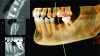
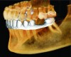
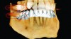
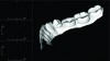
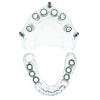
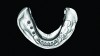
The cone beam data set is the primary layer and the optical scan gets overlaid as another visual layer, similar to the multiple layers of images in photo-editing software packages such as Adobe Photoshop. Each layer can be viewed and manipulated independently from the other layer, which multiplies the visual capabilities of both data sets alone. The CBCT data provides the skeletal and dental backdrop to the image so that implants can be placed with 3-D precision in the available anatomy. Critical boundary conditions, such as the sinuses, nerves, and cortical boundaries, can be clearly visualized.8-11 Moreover, when the optical scan is added as an additional layer, this opens up a new element of patient data that can be used for enhanced treatment planning beyond the already advanced 3-D planning of CBCT by itself (Figure 3). This new optical scan layer of patient data provides highly detailed views of intraoral anatomy, such as the gingiva, mucosa, and detailed boundaries of both adjacent and opposing dentition.12 CBCT images by themselves can have a limitation with dental anatomy usually because of restorations that cause metallic scatter (Figure 4). The optical scan surpasses this limitation and also provides critical information about the soft tissue, which is also lacking in CBCT data by itself. In addition, another benefit of the optical scan data is the very high resolution that it provides of the intraoral data. Therefore, this is very important when surgical guides are created, as the fit and accuracy of the guide is dependent on the quality and resolution of the intraoral data.13 Surgical guides made solely from CBCT data are more prone to fit issues during surgery, such as rocking or being too tight or too loose.
The optical scan itself becomes a new layer onto which other layers can be added; the next two layers are usually virtual restorations and virtual abutments. Jaw tracking and articulation are also possible and more capabilities in this domain are currently being developed. Software packages that allow for CBCT and optical scan fusion to occur also allow for virtual restorations to be added similar to how virtual implants are added into the CBCT data (Figure 5). Very accurate digital restoration designs can be created in edentulous spaces, which allows for ideal placement of implants for truly restorative-driven treatment planning. Treatment planning with proper occlusal trajectories for ideal restorative function is easier to achieve with this integrated information.14
When compromises between the skeletal placement of an implant and placement for its ideal restorative position occurs, the planner can determine whether or not custom abutments can be used to solve the discrepancy or if the implant’s location, angulation, or size should be modified instead. This can be accomplished with the visualization of a virtual abutment and modifying its design. Visualizing the implant trajectories with the virtual restoration can also aid in the determination ahead of time if screw-retained restorations are possible (Figure 6). This integrated data provides communication benefits as well. It allows for a higher level of communication between colleagues and enhanced patient education and presentation. All of the elements are digital and can be viewed dynamically in the 3-D software, or captured as standard digital images for easier sharing and viewing by other team members and providers.
As an alternative to virtual restorations, physical wax-ups of the proposed restorations can be performed on stone models, which can then be optically scanned. This allows for the restoration visual to automatically be a part of the initial optical scan acquisition process. If models are scanned with and without the wax-up, each element can be separated in the software as its own layer. In the past, patients wore radiographic scanning templates with radiopaque wax-ups to help visualize the proposed occlusion with the CBCT scan. The limitation of this technique was that it was not layered, and all of the data were in one volume that could not be individually viewed or modified separately. Now, with modern fusion techniques and virtual designs, all of the elements are individual units that can be separated as their own layer that can be viewed in any combination.15
If a dentist does not have an optical scanner, standard physical stone models can be sent to the surgical guide company to be optically scanned with desktop scanners. The benefit of this technique is that it makes surgical guides, virtual restorations, and virtual abutment planning possible. However, the downside of this technique is that optical scans of stone models still require impressions, which can incorporate and perpetuate errors into the downstream manufacturing of surgical guides. If subpar impression and/or model pour-up techniques are employed, this will create a weak link in the entire chain. The entire process and end result are completely dependent on the quality of the data that goes into them; therefore, quality control is of the utmost importance. It is important to highlight that the majority of problems with surgical guides not working the way they are planned is a consequence of starting the process with poor data.16
For fully edentulous cases, the optical scan of the arch or stone model is still used to capture the mucosal anatomy. However, additional information is needed to help with the restoration planning. The best method currently involves duplicating the patient’s existing dentures with radiopaque material and having them wear that during the CBCT scan. The material has a radiopacity much greater than the mucosa and, thus, a precise line will show where the mucosa ends and the denture starts (Figure 7). Also, the radiopaque duplicate denture will show the occlusal surfaces of the prosthesis, which allows for implant planning to be performed with proper locations and trajectories for stability and function of the final prosthesis. Truly restorative-driven treatment planning may be achieved in this manner for edentulous cases as well.17
Manufacturing with STL Files
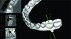
All of these various imaging layers provide manufacturing options that go beyond just visualization and virtual planning capabilities. Different layers can be singled out for specific manufacturing tasks. Optical scans and virtual models of implants, restorations, and abutments are different types of 3-D data elements than volumetric CBCT data. CBCT data is one big volume with no inherent boundaries delineating structures from each other. When looking at a cross-section of a CBCT scan, anatomical boundaries can be seen but there is no clear-cut dividing line inherent within it that defines where a particular structure ends and another begins. Optical scans and virtual planning models are different in that they are 3-D models with exact delineated surfaces. In fact, that is all they are because they have no internal volume and are strictly hollow models with defined surface boundaries. When viewed in cross-section, they are empty inside with a shell-like boundary on the outside (Figure 8). This is, in fact, not a limitation but simply a characteristic that allows for 3-D printing equipment to manufacture them; the machine can identify where the edges of the models are located. The file type of optical scans and virtual models is typically the nonproprietary .STL file format. It should be noted that some systems may limit the exporting capabilities of models as nonproprietary .STL files if they have an interest in or a need to control either certain aspects of or the entire the manufacturing process.
When implant plans and virtual restorations and abutments are designed together, they all can be manufactured for use in conjunction with surgical guides so that everything fits together in the clinical situation. When all of the elements are planned out ahead of time, they may all synergistically come together in real life when 3-D manufacturing is involved. The implant plan within the CBCT scan is used in conjunction with the optical scan to create a surgical guide that will facilitate the placement of the implants in the exact preplanned location.17 If custom abutments were designed, they can be manufactured to be used for that exact predetermined implant location and angulation. Designed restorations can also be manufactured and used immediately as provisional restorations. The initial restoration design can be used to dial in the final restoration design but a second optical scan is still needed as the final digital impression. Even with surgical guides there can be slight positional changes in the placement of the implant that would cause seating and contact issues of a pre-manufactured final restoration. Once the implants are placed and a final impression is acquired the final restoration can be milled with either in-office systems or lab-based equipment. For multiunit fixed cases, the framework is also digitally designed after the implants are placed and after the final impression is captured.
Surgical Guides—Bringing Virtual Treatment Plans to Life
The surgical guide plays the central role of connecting and synchronizing all of the preplanned digital elements together in the operatory (Figure 9). Once the implants are planned with the combined CBCT and optical scan data, a surgical guide can be ordered and used to achieve the virtual plan in real life.18-20 Surgical guides can be created with different levels of control; the more control available, the closer the actual surgery will match the digital plan. The most basic level of control is a pilot guide that will only guide the location and angulation of the pilot drill in the surgical sequence. The rest of the drill sequence and the final implant placement are done freehand. Pilot guides are a good way to start out with proper locations and angulations but they do not guarantee that the final placement will exactly match the preplanned position; subsequent implant drills in the sequence can veer off slightly from the planned angulation. The next level of control is drill sequence control, which guides all subsequent drills in the sequence so that the final location of the implant is as close as possible to the preplanned position. Depth control is also possible to ensure that drills do not exceed the planned apical location of the implant and it also helps to achieve the exact crestal position as well. Lastly, another level of control is implant guidance control, where the surgical guide would allow the actual implant to be placed through it. This final level of control is limited based on the implant shape and design and also the surgical guide system being used. As a result, it is very common for the implant itself to be placed freehand without the use of the surgical guide.
Provisional Restoration Guidance Techniques
The more control that a surgical guide has, the closer the actual surgery will match the virtual one. This is important when trying to connect the final implant position to match the virtual abutments designed for that location and angulation and/or pre-made provisional restorations. Another level of control that can be achieved with surgical guides is termed provisional restoration guidance. There are two main techniques that are currently used to connect implant planning and placement with provisional restorations directly after implant surgery. The first technique uses a stereolithographic printout of the optical scan of the patient’s arch, but with the addition of holes in the locations where the implants are virtually planned. These holes are the receptor sites for implant analogs, which can be used to create provisionals on top of them using standard laboratory methods. Thus, this model is typically called an analog model (Figure 10). This technique uses the surgical guide to achieve the exact preplanned location of the implants and then the provisional restorations can be placed immediately after surgery. This technique of creating provisions on analog models can be performed in-office; however, it is advantageous to work with a laboratory at this point in time not only for their expertise but also to minimize working time in the office that could be used for direct patient care. The analog model is typically sent to the laboratory for the provisionals to be made. The second technique involves a completely digital process in which the provisional restorations are designed using a digital analog model and specialized CAD/CAM software. The design is then manufactured with 3-D printing or milling equipment with biocompatible materials to make the provisional restorations. Once the final optical scan is captured, these same designs can be modified into the final restorations.
Conclusion
While that the entire process may seem very technical and challenging to accomplish, fortunately the amount of work the clinician has to do is minimal because most of the technical steps are handled by either the surgical guide company or the laboratory. Dental auxiliaries typically perform data acquisition, which makes the dentist’s workflow simple and straightforward. All of data that are captured by the auxiliaries are then forwarded to the surgical guide company for the data-integration process. Thereafter, the integrated data is relayed back to the dentist, which is usually the first time that he or she will interact with it. At this point in time, the dentist can perform 3-D implant planning in a matter of minutes and, subsequently, save the treatment plan and send it back to the surgical guide company for manufacturing of the surgical guide. Virtual restoration planning at this time is also very simple and usually takes only a few minutes. The dentist can design custom abutments and provisional restorations but they are usually passed along to the laboratory after the implant plan is finished. The surgical guide and analog model are both created by the surgical guide company. The laboratory then uses the analog model to make the provisional restorations. Thereafter, the provisional restorations are sent to the dentist who may use the surgical guide to place the implants and then seat the provisionals. Hence, the entire technical process only involves the dentist at the point of virtual implant planning and the actual implant surgery, and every other aspect is taken care of by the surgical guide company and the laboratory. The end result is a restorative-driven implant plan that is brought to life through the use of integrated imaging technologies, which is far superior to treatment planning that does not use integrated imaging data.
About the Author
Douglas L. Chenin, DDS
CEO
Clinically Correct Inc.
Moraga, California
References
1. Kau CH, Li J, Li Q, Kheir NA. Update on cone beam technology and orthodontic analysis. Dent Clin North Am. 2014;58(3):653-669.
2. Kau CH. Creation of the virtual patient for the study of facial morphology. Facial Plast Surg Clin North Am. 2011;19(4):615-622.
3. Chenin DL, Chenin DA, Chenin ST, Choi J. Dynamic cone-beam computed tomography in orthodontic treatment. J Clin Orthod. 2009;43(8):507-512.
4. Ganz SD. The next evolution in CBCT: Combining digital technologies. Inside Dentistry. 2013;9(2):116-118.
5. Halperin-Sternfeld M, Machtei EE, Horwitz J. Diagnostic accuracy of cone beam computed tomography for dimensional linear measurements in the mandible. Int J Oral Maxillofac Implants. 2014;29(3):593-599.
6. Hatcher DC, Dial C, Mayorga C. Cone beam CT for pre-surgical assessment of implant sites. J Calif Dent Assoc. 2003;31(11):825-833.
7. Ritter L, Reiz SD, Rothamel D, et al. Registration accuracy of three-dimensional surface and cone beam computed tomography data for virtual implant planning. Clin Oral Implants Res. 2012;23(4):447-452.
8. Mora MA, Chenin DL, Arce RM. Software tools and surgical guides in dental-implant-guided surgery. Dent Clin North Am. 2014;58(3):597-626.
9. Worthington P, Rubenstein J, Hatcher DC. The role of cone-beam computed tomography in the planning and placement of implants. J Am Dent Assoc. 2010;141(Suppl 3):19S-24S.
10. Benavides E, Rios HF, Ganz SD, et al. Use of cone beam computed tomography in implant dentistry: the International Congress of Oral Implantologists consensus report. Implant Dent. 2012;21(2):78-86.
11. Ganz SD. Cone beam computed tomography-assisted treatment planning concepts. Dent Clin North Am. 2011;55(3):515-536.
12. Scherer M. Presurgical implant-site assessment and restoratively driven digital planning. Dent Clin North Am. 2014;58(3):561-595.
13. Balasundaram A, Gurun D, Neely A, et al. Novel CBCT and optical scanner-based implant treatment planning using a stereolithographic surgical guide: a multipronged diagnostic approach. Implant Dent. 2014;23(4):401-406.
14. Chenin DL. Implant planning software. In: Tamimi DF, ed. Specialty Imaging: Dental Implants. 2014; Salt Lake City, UT: Amirsys Publishing, Inc.
15. Lee CY, Ganz SD, Wong N, Suzuki JB. Use of cone beam computed tomography and a laser intraoral scanner in virtual dental implant surgery: part 1. Implant Dent. 2012;21(4):265-271.
16. Chenin DL. Surgical guides. In: Tamimi DF, ed. Specialty Imaging: Dental Implants. 2014; Salt Lake City, UT: Amirsys Publishing, Inc.
17. Friedland B, Danoff B, Chenin D. Virtual technologies in dentoalveolar evaluation and surgery. Atlas Oral Maxillofac Surg Clin North Am. 2012;20(1):37-52.
18. Park C, Raigrodski AJ, Rosen J, et al. Accuracy of implant placement using precision surgical guides with varying occlusogingival heights: an in vitro study. J Prosthet Dent. 2009;101(6):372-381.
19. Jabero M, Sarment DP. Advanced surgical guidance technology: a review. Implant Dent. 2006;15(2):135-142.
20. Schneider D, Marquardt P, Zwahlen M, Jung RE. A systematic review on the accuracy and the clinical outcome of computer-guided template-based implant dentistry. Clin Oral Implants Res. 2009;20(Suppl 4):73-86.