You must be signed in to read the rest of this article.
Registration on CDEWorld is free. Sign up today!
Forgot your password? Click Here!
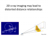
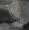
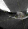
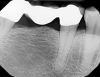
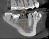
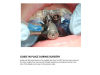
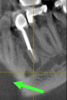
For more than 100 years, two-dimensional radiographic imaging has been a standard diagnostic tool in dentistry despite the inherent limitation of viewing a three-dimensional (3D) object in two dimensions (2D). A two-dimensional view creates superimposition and distortion of the distance between structures (Figure 1 and Figure 2). In the 1970s, computerized axial tomography, or CAT scans, became available for 3D imaging but had limited use in dentistry because of high radiation dosages, cost, and accessibility issues. With the commercial introduction of cone-beam computed tomography (CBCT) in 2001, dentists have found it practical to perform 3D imaging in the dental office and it has been increasing in use.1 In 2003, Hashimoto et al reported that the one CBCT unit produced better image quality with a much lower radiation dose than the newest multidetector-row helical CT unit (1.19 mSv vs 458 mSv per examination).2
During imaging, the CBCT scanner rotates around the patient’s head to obtain anywhere from 150 to 600 distinct cross-sectional images. The images are reconstructed into a 3D volumetric data set called a digital volume. This is accomplished with a modification of the original cone-beam algorithm. The digital volume is composed of 3D voxels (a 3D measurement on a grid) of anatomical data that can be manipulated and visualized with special software.3
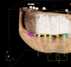
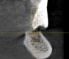
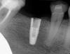
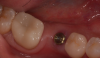
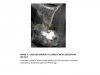
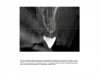
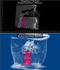
Over the past 15 years, many manufacturers have introduced models with improved resolutions, decreased scatter from metal restorations, and new features that limit radiation dosage and offer variable fields of view.4 CBCT software is constantly advancing, allowing more sophisticated planning for implant treatment, orthodontics, orthognathic surgery, airway management, and occlusal appliance therapy. With the ability to merge digital data from intraoral scans, extraoral scans (facial), and jaw-motion recordings, it is now possible to create a “virtual digital” patient. This is expanding the traditional use of CBCT diagnosis into new areas (Figure 3 and Figure 4).
Implant Planning and Placement
The 3D imaging of bone has always been recognized as an important adjunct to implant treatment.5 The ability to identify anatomic structures, bone volume, root proximity, and pathology makes implant treatment more predictable and efficient.6 Because of the costs, radiation exposure, and limited access, medical CAT scans were used mostly for complex cases. With the introduction of dedicated dental CBCT devices, these limiting factors were mitigated.
CBCT can produce detailed and precise 3D images of teeth, jaw, bones, nerves, and soft tissues. Anatomic structures that are important for implant placement include the mandibular nerve, mental and incisive foramen, and maxillary sinuses, as well as concavities in the bone. CBCT is also helpful in identifying pathology such as periapical pathology, radiolucencies and opacities, root fractures, cysts, and sinus pathology that may impact implant treatment.7
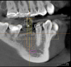
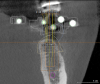
With 3D data, it is often possible to find adequate bone for implant placement with no or minimal grafting (Figure 5, Figure 6, Figure 7, Figure 8, and Figure 9). Even in situations where grafting will be beneficial, there are advantages to knowing in advance. Scheduling and inventory can be done accurately, minimizing wasted time and materials. Patients know beforehand what to expect postoperatively, as well as total treatment time and cost.
Since the inception of 3D imaging, clinicians have figured out ways to make surgical guides to allow surgeons to place the implants where they were planned on the scan. Initially, the process was cumbersome, costly, and time consuming, and it was reserved for the most complex cases. Multiple scans and expensive, labor-intensive laboratory work was required. With the ability to integrate digital data from oral scans and advances in software, the process of fabricating precision surgical implant guides has become easy, fast, and more cost-effective.8 The integration of CBCT and CAD/CAM intraoral scans has simplified the planning and fabrication of precision surgical guides so that implant placement can be planned “top down” (Figure 10, Figure 11, Figure 12, Figure 13, Figure 14, Figure 15, Figure 16, Figure 17, Figure 18, Figure 19, and Figure 20). The final restoration can be “virtually” planned in minutes in the CAD/CAM program and merged with the CBCT data. The implant is then “virtually” placed in the CBCT so that an ideal emergence of the final restoration can be achieved. A precision guide is milled and used to place the implant in the planned location.9 Often it is possible to place the implant through a tissue punch, further minimizing the manipulation of soft tissue. Patients experience less swelling and discomfort and appreciate the shorter time in the dental chair.10 Surgeons can make efficient use of their chair time and reduce the stress that occurs when encountering unexpected clinical situations. The clinical staff can have the correct implants on hand for the surgery, reducing their inventory or the need to modify treatment based on which implants are in stock. The administrative team can more predictably and efficiently schedule patients as surgeries run into fewer “unplanned” modifications.
With the information garnered from the CBCT scans, the surgeon can better estimate whether multiple surgical procedures will be needed, whether grafting will be needed and, if it is needed, what materials to have on hand as well as which implant is most appropriate. For the practitioner, this leads to more accurate scheduling as there is less need to build in “cushion time” for unexpected grafting procedures. This information also allows for inventory control because the proper implant can be ordered and set aside in advance. For example, by using 3D data a clinician may realize that a tapered design might be the right choice where there is a buccal concavity that could not be seen on a 2D image. Having the proper implant leads to less stress during surgery, and, most importantly, a better outcome for the patient because the proper implant can be placed with the least amount of surgery.11
The integration of 3D imaging and CAD/CAM intraoral scanning is enabling dentists to place implants with the most complete information.12
Oral Surgery
An historical challenge in wisdom tooth extraction and other surgical procedures has been evaluating the risk for mandibular nerve and sinus trauma and the cost/benefit analysis of extraction. Two-dimensional imaging results in superimposed structures, making visualizing teeth or pathology in their true 3D relationship to anatomic structures, such as the mandibular nerve and sinuses, difficult. Even something as basic as root anatomy can be difficult to evaluate in 2D, leading to complications and stress when what seemed like a simple extraction becomes more involved. Three-dimensional planning and guides have become important in orthognathic surgery and are the standard of care in many hospitals. As with implant surgery, the ability to accurately plan the surgery in advance “virtually” and then carry out the surgery with guides and stents makes the procedure faster and more predictable. As well, 3D imaging has become the standard of care in many oral surgery situations such as evaluating pathology, grafting, and reconstruction (Figure 21).13
Endodontics
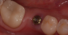
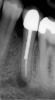
Manufacturers have introduced CBCT systems with a smaller field of view, which reduces exposure, and is ideal for endodontics, in which the area of interest is usually one or two teeth.14 Three-dimensional imaging has been shown to be effective for helping the clinician find additional canals and certain types of root fracture as well as to visualize radiolucencies around teeth (Figure 22, Figure 23, Figure 24, Figure 25, Figure 26, Figure 27, Figure 28, Figure 29 and Figure 30).15 CBCT data provide additional diagnostic information about blocked canals, strip perforations, and proximal bone loss, which leads to appropriate treatment, ultimately saving patients from failed procedures and associated costs (Figure 31 and Figure 32).16
Orthodontics
With the development of low-dose machines, the exposure from CBCT can be comparable to a combined panorex and cephalometric, while providing more diagnostic data.17 Being able to evaluate impacted teeth and their surroundings can influence treatment decisions for how or if to move teeth. In addition to providing the traditional diagnostic information, CBCT scans can offer information about airways and sinuses. Many orthodontists are recognizing the importance of helping their young patients develop adequate airway space.18
CBCT provides a 3D view of the airway and there is software that allows the clinician to measure the cross section of the airway at multiple levels and visualize the area of greatest constriction. This in an emerging application and as more data is gathered, clinicians will have guidelines for how repositioning the mandible influences the airway and where the jaws need to be positioned for an adequate airway. At this time, this information can identify patients with a likelihood of having a restricted airway. This may influence decision-making on whether or not to remove tonsils.18 For example, in a patient with an inadequate airway, the orthodontist may choose mandibular advancement over restricting the airway further with maxillary retraction. Additional digital data from facial scans can be integrated with the CBCT data so that orthodontists can evaluate the impact of their treatment on facial esthetics.
Periodontics
While research has shown the accuracy of CBCT scans in helping to evaluate bony defects, at this time, it has not gained widespread acceptance in periodontal diagnosis. CBCT can be a useful adjunct in certain situations such as evaluating bony defects and furcations. The bony contour of defects affects the type and success of grafting, so having this information before surgery is valuable for treatment planning, scheduling, and patient understanding of the surgical procedure (Figure 33).19
Temporomandibular Joint
CBCT provides an accurate image of the bony condyle, bony fossa, and their spatial relationship, and can be essential for evaluating arthritic or other changes to the temporomandibular joint (TMJ). The relationship between the condyle and fossa is also captured, though this is influenced by the position of the mandible during scanning. Data from 3D tracking devices, merged with the CBCT data, can show how the condyle moves in relation to the fossa. The software allows for the design and construction of occlusal splints that are based on the condylar position. The mandible is “virtually” positioned in the software and the stent is made to the selected position. The “new” condylar position can be visualized on the CBCT. Dentistry has had many theories on proper condyle position from a retruded “centric relation” position to a neutral “habitual” position to a more forward “airway centric” position.20 With CBCT and the ability to visualize the condyle/fossa relationship in action, we may finally get scientific data on this controversial topic (Figure 34).18
Airway
Inadequate adequate airway space in both children and adults has been identified as a major health issue with serious consequences including heart disease, high blood pressure, memory loss and early dementia.21 Many dentists make mandibular repositioning appliances for sleep apnea, and more orthodontists are becoming aware of the importance of helping young patients develop adequate airway space. There are software programs that use the CBCT data to measure actual airway volume along the airway and identify the area of maximum restriction. Diagnostic software can show the increase in airway space for a given amount of jaw protrusion. While new, it shows great promise for patient care and an increased role for dentists in treating this growing problem.22
Discussion
In the 15 years that CBCT has been available in dentistry, it has gone from being a new technology with limited application, to being a “core” technology that has a prominent place in treatment planning. Every dentist should at least understand the benefits and the clinical situations where CBCT is appropriate as well as have the ability to read and evaluate a CBCT image. As patients, we understand the benefits of MRIs, CAT scans, and other 3D imaging modalities. As clinicians, it is important to provide that diagnostic information to our patients and incorporate CBCT into our practices, because 3D data provides improved diagnosis and treatment planning in so many clinical situations.
Conclusion
CBCT gives dentists the ability to view and evaluate the head and neck in 3D. CBCT is already the standard of care for some clinical situations, and the number of applications will continue to grow. As the technology progresses, diagnostic information increases and exposure decreases. Advances in software along with the integration of data from oral scans, face scans, and jaw motion sensors allow for more applications. The creation of a digital “virtual patient” has opened new treatment possibilities which dentistry is just beginning to explore.
About the Authors
Dr. Andrew Koenigsberg founded the Manhattan group practice Gallery57Dental. A graduate of Columbia University School of Dental and Oral Surgery, Dr. Koenigsberg has himself taught predoctoral students at Columbia as well as postgraduate students maxillofacial prosthetics at Montefiore Hospital’s Postgraduate Prosthodontics program. In 2010 he cofounded CAD/CAM Excellence, a continuing education center, where he is clinical director.
Dr. Rebecca Koenigsberg is a graduate of Columbia University College of Dental Medicine, and completed a 1-year General Practice Residency at Montefiore Medical Center. She is one of the first dentists in New York to be certified in the use of the Solea laser technology, allowing her to treat many patients without the use of a drill or injection.
Disclosure
The authors report no conflicts of interest with the material presented in this course.
References
1. Katsumata A, Hirukawa A, Okumura S, et al. Relationship between density variability and imaging volume size in cone-beam computerized tomographic scanning of the maxillofacial region: an in vitro study. Oral Surg Oral Med Oral Pathol Oral Radiol Endod. 2009;107:420-425.
2. Hashimoto K, Arai Y, Iwai K, et al. A comparison of a new limited cone beam computed tomography machine for dental use with a multidetector row helical CT machine. Oral Surg Oral Med Oral Pathol Oral Radiol Endod. 2003;95:371-377.
3. De Vos W, Casselman J, Swennen GR. Cone-beam computerized tomography (CBCT) imaging of the oral and maxillofacial region: A systematic review of the literature. Int J Oral Maxillofac Surg. 2009;38(6):609-602.
4. Scarfe WC, Farman AG, Sukovic P. Clinical applications of cone-beam computed tomography in dental practice. J Can Dent Assoc. 2006;72:75-80.
5. Schulze R, Heil U, Grob D, et al. Artifacts in CBCT: a review. Dentomaxillofac Radiol. 2011;40:265-273.
6. Benavides E, Rios HF, Ganz SD, et al. Use of cone beam computed tomography in implant dentistry: the International Congress of Oral Implantologists consensus report. Implant Dent. 2012;21(2):78-86.
7. Abrahams JJ, Dental CT. Imaging: a look at the jaw. Radiology. 2001; 219:334-345.
8. Borgonovo AE, Rigaldo F, Battaglia D, et al. Digital device in postextraction implantology: A clinical case presentation. Case Reports in Dentistry. 2014;327368. October 2015. http://dx.doi.org/10.1155/2014/327368.
9. Prashant P Jaju, Sushma P Jaju. Clinical utility of dental cone-beam computed tomography: current perspectives. Clin Cosmet Investig Dent. 2014;6:29-43.
10. Orentlicher G, Abboud M.Guided surgery for implant therapy. Dent Clin North Am. 2011;55(4):715-44.
11.Worthington P, Rubenstein J, Hatcher DC. The role of cone-beam computed tomography in the planning and placement of implants. J Am Dent Assoc. 2010;141:19S–24S.
12. Patel N. Integrating three-dimensional digital technologies for comprehensive implant dentistry. J Am Dent Assoc. 2010;141(2):20S–24S.
13. Kim HG, Lee JH. Analysis and evaluation of relative positions of mandibular third molar and mandibular canal impacts. J Korean Assoc Oral Maxillofac Surg. 2014;40(6):278-284.
14. Wang P, Yan XB, Lui DG, et al. Detection of dental root fractures by using cone-beam computed tomography. Dentomaxillofac Radiol. 2011;40(5):290-298.
15. Kambungton J et al. Assessment of vertical root fractures using three imaging modalities: cone beam CT, intraoral digital radiography and film. Dentomaxillofac Radiol. 2012;41(2):91-95.
16. Scarfe WC, Levin MD, Gane D, Farman AG. Use of cone beam computed tomography in endodontics. Int J Dent. 2009;2009:634567.
17. Carlson SK, Graham J, Mah JM, et al. Let the truth about CBCT be known. Am J Orthod Dentofacial Orthop. 2014;145(4):418-419.
18. Machado GL. CBCT imaging–a boon to orthodontics. Saudi Dent J. 2015;27(1):12-21.
19. Borges GJ, Ruiz LFN, de Alencar AHG, et al. Cone-beam computed tomography as a diagnostic method for determination of gingival thickness and distance between gingival margin and bone crest. The Scientific World Journal. 2015(2015):142108. http://dx.doi.org.10.1155/2015/142108.
20. Sener S, Faruk A. Correlation between the condyle position and intra-extraarticular clinical findings of temporomandibular dysfunction. EurJ Dent. 2011;5(3):354-360.
21. Victor LD. Obstructive sleep apnea. Am Fam Physician. 1999;60:2279-2286.
22. Ghoneima A, Kula K. Accuracy and reliability of cone-beam computed tomography for airway volume analysis. Eur J Orthod. 2013;35(2):256-261.