You must be signed in to read the rest of this article.
Registration on CDEWorld is free. Sign up today!
Forgot your password? Click Here!
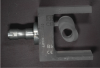
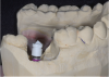
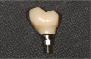
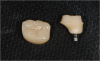
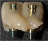
Computer-aided design and computer-aided manufacture (CAD/CAM) refers to the process of using digitalized data to design and manufacture objects. Originally used in drafting and engineering applications, in dentistry CAD/CAM has been used to scan teeth in the mouth or scan models in the laboratory in order to manufacture dental restorations. The types of restorations that can be manufactured using CAD/CAM have expanded from single crowns to implant abutments and full-arch prostheses as well as orthodontic appliances, occlusal splints, and dentures. Because plastic devices can be milled or printed, CAD/CAM is also being used to manufacture surgical guides for implant placement. Because of CAD/CAM’s efficiency, precision and simplified workflow, most custom implant abutments and frameworks are now being manufactured using this technology (Figure 1).
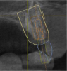
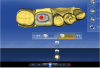
Cone-beam computerized tomography (CBCT)1 provides a three-dimensional (3D) image of the hard tissues of the jaws. Some machines are equipped to provide a larger field of view and include additional structures of the head and neck. There are many software programs that enable implant surgery to be virtually planned on the 3D image, allowing for visualization of the implant in the surrounding bone (Figure 2). A temporary or final prosthesis can be manufactured using CAD/CAM or conventional techniques before the surgery is performed. At this time, most programs allow for a guide to be fabricated from a surgical plan, ensuring implant placement in the exact position that was planned.2
These technologies make implant placement simpler, more precise, less traumatic, and faster and should be incorporated into practices. Implant treatment has been rapidly evolving on many fronts, making it challenging for practitioners to stay current. Implants have been evolving with new shapes, surface coatings, thread design, prosthetic connections, sizes, etc. Surgical techniques also have advanced so that clinicians are now often able to place implants at the time of extraction and immediately load them. Bone grafting and sinus augmentation has become routine and predictable.3 Digital technologies are part of the advances that are occurring in implant therapy. These technologies not only require new knowledge and skills (such as choosing the most suitable thread design for a particular situation or learning how to place an implant in an extraction site), but they may require a significant monetary investment in equipment.
Simplified Treatment with Integrated Digital Implant Technologies
Implant therapy can be divided into four phases: diagnosis, treatment planning, placement, and restoration. Each of these stages can be improved using digital technology.
Diagnosis
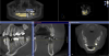
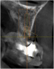
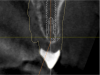
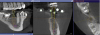
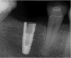
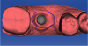
The ability to visualize the jaw in 3D has long been recognized as an advantage in implant therapy, because 3D imaging allows for the assessment of the quantity, position, and quality of the bone as well as anatomic structures such as the mandibular nerve and maxillary sinuses (Figure 3).4 It also allows for assessing areas of pathology, residual roots, concavities, and anomalous structures (Figure 4). Historically, medical-grade computerized axial tomography (CAT) imagers were used to gain 3D visualization of the hard tissues. Some of the limitations of the medical CAT scans were expense and radiation level as well as lack of availability in dental offices. The image was on film or paper, limiting the precision of planning and ability to transfer the plan to surgical guides. While ingenious practitioners devised methods to work around these limitations to create surgical guides, their cost was so high and their workflow so cumbersome, that use of these scans was limited to complex and challenging cases. With the introduction of office-based CBCTs, radiation doses have been significantly reduced and the workflow has been simplified.5 There are now many software programs that allow for virtual implant surgery on the 3D image. The surgery can be planned and the guide ordered in minutes. 3D imaging is rapidly emerging as the standard of care for implant therapy.6
Treatment Planning
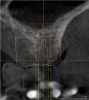
CBCT 3D data and planning software have significant treatment-planning advantages over 2D data. The surgeon can see all of the available bone and virtually place implants in the image. The surgeon can easily switch implant length, width, angulation, depth, and even the manufacturer to get the best placement for a given clinical situation.7 Rather than settle for the best implant in stock, the surgeon can select the best implant for a given clinical situation and order it in advance, minimizing inventory costs. The surgeon can determine in advance if there is enough bone for implant placement, or if grafting is going to be needed first. The surgeon may decide that the implant can be placed and whether supplemental grafting will be needed at the time of implant placement (Figure 4). This allows the patient to have realistic expectations as to what the surgery involves and what the recovery will entail, as well as what the cost will be and how long the process will take until final restoration.8
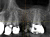
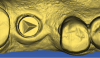
It is now possible with many systems to merge data from the CBCT and a CAD/CAM file. CBCT allows clinicians to visualize the bone while CAD/CAM captures the soft tissue as well as a more accurate representation of the teeth, especially if there are metal restorations, which distort the CBCT image (Figure 5). CAD/CAM also allows clinicians to virtually place the final restoration so that the implant can be planned top-down, in relation to the final restoration. This has several treatment-planning implications.
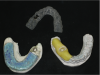
In the anterior region, the position of the implant is critical to achieving proper soft-tissue support and an esthetic result for the final restoration.9 The merged data allows ideal implant placement relative to the contacts, soft tissue, and buccal profile of the restoration. If a screw-retained crown is desired, the implant should be placed so that the long access emerges through the cingulum. This may require bone grafting, which can be planned in advance. Alternatively, one can choose an implant with the option of angle correction, allowing for a screw-retained single unit. At this time, there are only two implants that have this feature, the NobelReplace® conical connection (www.nobelbiocare.com) and the Straumann® Bone Level connection (www.straumann.us) (Figure 6). With the merged data from the CBCT and the CAD/CAM program, the best choice is planned for and obtained in advance of the surgery as opposed to the surgeon being forced to do “the best he or she can” with the inventory he or she happens to have in the office.
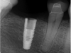
In the posterior region, knowledge of the position of anatomic structures, such as the mandibular nerve and maxillary sinuses, is critical in planning the surgery and selecting the proper implant. An ever-increasing selection of implant shapes reduces the need for grafting in many situations if implant selection and position are precisely planned and executed. In cases where grafting is appropriate it is known ahead of the surgery, which allows for better patient management by informing the patient about cost, healing expectations, and treatment length. The posterior region can allow for more flexibility on where to place the implant because esthetics is less of a concern. Shifting the implant a few millimeters anteriorly or posteriorly may obviate the need to graft (Figure 7). If a screw-retained restoration is the goal, the mesiodistal insertion axis is critical. The path of insertion of the final restoration is dictated by the abutting contacts. Even a slight deviation of a few degrees between the long axis of the implant and the insertion path dictated by the contacts can negate the option of making a screw-retained crown (Figure 8).
In the digital planning process, both the virtual CAD/CAM tooth (ie, the final restoration) and implant position can be easily, quickly, and inexpensively modified, making changes to the plan simple and efficient. With merged digital data and a guide, the surgeon, restorative doctor, and patient can make an informed decision before surgery. This lowers the stress level of the surgery and is more efficient for the office as the proper amount of time is scheduled. The surgeon and restorative dentist can collaborate online and the guide can sometimes be ordered online with no model sent to the laboratory, further simplifying the workflow.10
Implant Placement
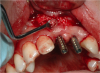
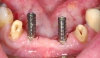
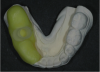
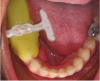
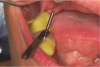
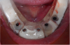
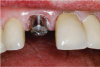
CAD/CAM allows for accurate precision guides to be made from the virtual plan (Figure 9).11 These guides are used at the time of surgery to precisely direct the angulation and depth of the drills, creating the planned osteotomy in the bone.12 The implant can also be placed through the guide so that the implant is placed precisely where planned. These guides have been shown to be quite accurate and they significantly shorten and simplify the surgical procedure. While there is some variation between the planned position and the actual position,13 these variations should be acceptable if adequate safety margins are built into the plan.14 If there is adequate attached tissue, the surgery may be done through a tissue punch because there is no need to visualize the bone (Figure 10).15 This shortens the surgery and follow-up because no flaps are reflected or sutures placed. For the patient, there is reduced postoperative swelling, pain, and morbidity. Both the doctor and patient benefit from fewer visits because there are no sutures to remove or flap healing to observe.
In the past, surgical guides were made by having a tooth or teeth waxed up in an ideal position on a model and a guide made with the implant centered below. This was labor intensive, time consuming, and expensive. Often, the bone volume did not allow for the implant to be placed where the guide dictated because there was no way of accurately relating the bone volume to the implant placement. The surgeon was left to make a decision during surgery on whether to follow the guide—which may have compromised the implant—or to place the implant in a different area with more bone, which may have compromised the final restoration.
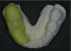
While guide fabrication has advanced since the simple guide described above and there are other methods for making guides, CAD/CAM is the most efficient, accurate, and cost-effective way to create a precision surgical guide.16 Depending on the system, the CAD/CAM guides may be milled or printed out of a rigid plastic. Sirona Dental Inc.’s CEREC® system (www.cereconline.com) uniquely allows for small guides to be produced in the office out of a thermoplastic material and a small milled insert (Figure 11). While this solution is only appropriate for some cases, it does allow guides to be made in minutes for about $30, enabling this procedure to be done for routine single implants in a cost- and time-effective manner. Laboratory-made guides can vary in cost from about $200 to $450 depending on the manufacturer and number of implants. With the integration of CAD/CAM and CBCT, guides have gone from an expensive, cumbersome, inaccurate adjunct to a routine part of the implant procedure (Figure 12).
Implant Restoration
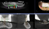
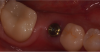
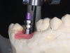
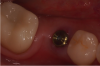
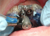
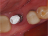
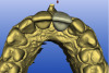
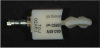
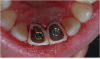
CAD/CAM impressions have been shown to be accurate.17 Impressioning implants is simplified with CAD/CAM because the shape of the implant is known and can be stored as a digital file. In contrast to impressioning prepared teeth where a unique shape must be captured, with implants it is necessary only to capture the position. Several companies make implant impression posts specifically for CAD/CAM that are screwed into the implant and scanned (Figure 13). BIOMET 3i’s BellaTek® Encode® (www.biomet3i.com) is a healing abutment that doubles as a scannable impression post so that it is not necessary to even place a separate impression post in most cases (Figure 14). The two variables that often lead to errors when taking implant impressions—the impression post not being seated and the impression post moving in the impression material—are eliminated when scanning an impression post. This simplifies and speeds the process while also making it more accurate and error-free.
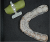
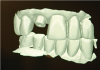
Restorations can be designed “virtually” with no analog model, which reduces costs as well as errors inherent to model fabrication (Figure 15). If a model is desired, with some systems it can be created by printing or milling.18
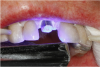
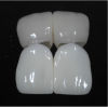
Over the last decade an increasing percentage of dental restorations have been fabricated through CAD/CAM because of its greater efficiency (Figure 16),19 and some of the newer ceramics can only be fabricated via CAD/CAM (Figure 17). Implant restorations—which include custom abutments, screw-retained crowns, bars, and implant-retained bridges—are particularly well suited to the CAD/CAM process because the materials commonly used (such as zirconium, lithium disilicate, chrome cobalt, and titanium) are best processed with CAD/CAM technology.20 When large metal frames are produced, CAD/CAM eliminates miscasts and other distortion which are very costly with implant laboratory work.20 These methods are more accurate than traditional casting.21
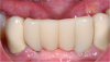
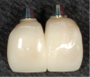
In some cases, the final restoration can be made before surgery when only the “virtual” model exists because the position of the implants and final restoration contours are known. While this is an advanced technique, it does illustrate the precision of the entire digital process. More commonly, CAD/CAM can be used to fabricate a temporary appliance in advance of the surgery because both the position of the implants and shape of the restoration are known (Figure 18). This can save time at the implant placement visit and provide a more esthetic temporary.
Advantages of Integrated Digital Implant Technologies
The process described above has several advantages to the patient. The patient may be able to visualize the final restoration before treatment begins.22 The surgery is often faster and less traumatic when it is done through a guide, especially if it can be done through a tissue punch and a flap can be avoided. Grafting can sometimes be avoided, saving the patient time and money as the restoration can usually be completed with less healing time. The final result should be better because the implant should be predictably placed in adequate bone with an easy-to-restore emergence position. Because the entire process is more predictable, the patient should have a better estimation of the time and costs involved for the entire implant treatment.
For the doctor, the simplified workflow leads to less stress, less clinical time, and a better result. Knowing how the entire process will unfold, from the surgery to the temporization to the final placement of the restoration, allows for better time management because there are fewer variables at every step. There is less uncertainty on whether grafting will be needed or what implant to have ready. A temporary can be prepared in advance. There is confidence that the implant will be in an adequate position for restoration and that the restoration can be completed simply and accurately.23
The laboratory phase is more accurate and predictable with “integrated digital implant technologies.” When the implants are planned from the “top down,” there should be enough room for the restoration, a common problem with poorly placed implants and a laboratory nightmare. When the implants are placed without regard to the final restoration, fabricating the prosthesis becomes a series of compromises that are often complicated or impossible to execute. Because of CAD/CAM’s efficiency, smaller laboratories can compete with larger laboratories to provide a customized service. Done this way, implant treatment is a great patient service and a profitable, predictable treatment.24
The disadvantage of digital technologies, both CAD/CAM and CBCT, is their upfront cost. While prices have come down in the last few years and more products are available, it is still expensive for the solo practitioner. This obstacle can be mitigated by integrating the technology into the practice’s workflow so that it is used enough to lower the per-use cost or by sharing the technology among several practitioners.
References
1. Marianella S, Vivas JL, Razzoog ME, Wang R-F. Precision of fit of titanium and cast implant frameworks using a new matching formula. Int J Dent. 2012(2012):374315.
2. Patel N. Integrating three-dimensional digital technologies for comprehensive implant dentistry. J Am Dent Assoc. 2010;141(Suppl 2):20S-24S.
3. Fornell J, Johansson LÅ, Bolin A, et al. Flapless, CBCT-guided osteotome sinus floor elevation with simultaneous implant installation. I: radiographic examination and surgical technique. A prospective 1-year follow-up. Clin Oral Implants Res. 2012;23(1):28-34.
4. Gupta J, Ali SP. Cone beam computed tomography in oral implants. Natl J Maxillofac Surg. 2013;4(1):2-6.
5. Jansen CE. CBCT technology for diagnosis and treatment planning: what general practitioners should consider. Compend Contin Educ Dent. 2014;35(10):749-753.
6. Tyndall DA, Price JB, Tetradis S, et al. Position statement of the American Academy of Oral and Maxillofacial Radiology on selection criteria for the use of radiology in dental implantology with emphasis on cone beam computed tomography. Oral Surg Oral Med Oral Pathol Oral Radiol. 2012;113(6):817-826.
7. Worthington P, Rubenstein J, Hatcher DC. The role of cone-beam computed tomography in the planning and placement of implants. J Am Dent Assoc. 2010;141(Suppl 3):19S-24S.
8. Benavides E, Rios HF, Ganz SD, et al. Use of cone beam computed tomography in implant dentistry: the International Congress of Oral Implantologists consensus report. Implant Dent. 2012;21(2):78-86.
9. Katsoulis J, Pazera P, Mericske-Stern R. Prosthetically driven, computer-guided implant planning for the edentulous maxilla: a model study. Clin Implant Dent Relat Res. 2009;11(3):238-245.
10. Balshi SF, Wolfinger GJ, Balshi TJ. Surgical planning and prosthesis construction using computer technology and medical imaging for immediate loading of implants in the pterygomaxillary region. Int J Periodontics Restorative Dent. 2006;26(3):239-247.
11. Valente F, Schiroli G, Sbrenna A. Accuracy of computer-aided oral implant surgery: a clinical and radiographic study. Int J Oral Maxillofac Implants. 2009;24(2):234-242.
12. Dreiseidler T, Neugebauer J, Ritter L, et al. Accuracy of a newly developed integrated system for dental implant planning. Clin Oral Implants Res. 2009;20(11):1191-1199.
13. Pettersson A, Kero T, Gillot L, et al. Accuracy of CAD/CAM-guided surgical template implant surgery on human cadavers: Part I. J Prosthet Dent. 2010;103(6):334-342.
14. Testori T, Robiony M, Parenti A, et al. Evaluation of accuracy and precision of a new guided surgery system: a multicenter clinical study. Int J Periodontics Restorative Dent. 2014;34(Suppl 3):s59-s69.
15. Bassetti M, Kaufmann R, Salvi GE, et al. Soft tissue grafting to improve the attached mucosa at dental implants: A review of the literature and proposal of a decision tree. Quintessence Int. 2015;46(6):499-510.
16. Nokar A, Moslehifard E, Bahman T, et al. Accuracy of implant placement using a CAD/CAM surgical guide: an in vitro study. Int J Oral Maxillofac Implants. 2011;26(3):520-526.
17. Güth JF, Keul C, Stimmelmayr M, et al. Accuracy of digital models obtained by direct and indirect data capturing. Clin Oral Investig. 2013;17(4):1201-1208.
18. Reich S, Kern T, Ritter L. Options in virtual 3D, optical-impression-based planning of dental implants. Int J Comput Dent. 2014;17(2):101-113.
19. Tahmaseb A, De Clerck R, Wismeijer D. Computer-guided implant placement: 3D planning software, fixed intraoral reference points, and CAD/CAM technology. A case report. Int J Oral Maxillofac Implants. 2009;24(3):541-546.
20. Drago CJ. Two new clinical/laboratory protocols for CAD/CAM implant restorations. J Am Dent Assoc. 2006;137(6):794-800.
21. Ortorp A, Jemt T, Bäck T, Jälevik T. Comparisons of precision of fit between cast and CNC-milled titanium implant frameworks for the edentulous mandible. Int J Prosthodont. 2003;16(2):194-200.
22. Marsango V, Bollero R, D’Ovidio N, Miranda M. Digital work-flow. Oral Implantol. 2014;7(1):20-24.
23. Zhao XZ, Xu WH, Tang ZH, et al. Accuracy of computer-guided implant surgery by a CAD/CAM and laser scanning technique. Chin J Dent Res. 2014;17(1):31-36.
24. Scherer MD, Kattadiyil MT, Parciak E, Puri S. CAD/CAM guided surgery in implant dentistry. A review of software packages and step-by-step protocols for planning surgical guides. Alpha Omegan. 2014;107(1):32-38.