You must be signed in to read the rest of this article.
Registration on CDEWorld is free. Sign up today!
Forgot your password? Click Here!
Dynamic navigation has been a tremendous boon to dental implant surgery, providing an advantageous alternative to freehand, static-guided, and robotic-guided surgery, as several studies have found that dynamic navigation has resulted in more accurate implant placement with more predictable outcomes.1-5Although static guides have provided improved clinical outcomes in implant therapy, they are also associated with certain workflow limitations,6including the need to design and fabricate the surgical guides via 3D printing in advance of the patient's procedure. This makes them less suitable for some clinical situations-for example, when there are shorter lead times to the planned surgical intervention or in emergency treatment situations. In general, limited mouth opening,7 narrow tooth gap situations, and deeper-placed implants are prohibitive for most static-guided designs,8 and static guides cannot be changed during surgery if the clinical situation warrants it. 9 Using a "virtual template" created in planning software, dynamic-guided navigational surgery, by contrast, can be planned and utilized within minutes; as such, it is amenable to alterations in planning and decision-making that may occur in real-time during the procedure. Dynamic navigation is more accurate and efficient than freehand surgery, while it has been found to offer accuracy of implant placement equivalent or similar to that provided by conventional static-guided and robotic surgery.2,3 The author recommends that dynamic navigation should therefore be used to guide implant placement for every implant in every patient who requires implant therapy. Its many advantages, coupled with the improved predictability and clinical outcomes it offers, help provide a greatly enhanced patient experience.
TECHNOLOGY AND USES OF DYNAMIC NAVIGATION
Computer-assisted surgery utilizes cone-beam computed tomo- graphy (CBCT), intraoral scanning, and 3D data with computer- based planning tools to implement surgical and restorative plans. The three types of computer-assisted surgery currently available are static-guided surgery, robotic surgery, and dynamic- guided navigational surgery. Dynamic navigation was first used for surgical procedures across a range of medical specialties,10 and more recently in dentistry, to avoid some of the limitations of static guides. Dynamic navigation features systems that allow real-time navigation and alteration of the treatment plan during surgery, serving as a virtual guide that employs light to guide freehand surgery using enhanced vision. Using systems that work with a 3D camera setup that records the position of the patient and the surgical instruments, during the surgical procedure dynamic-guided navigation displays the position of the drills onto CBCT images on a screen in real-time.11 The virtual template is preplanned through treatment planning software.
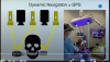
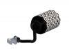
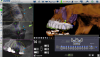
During the surgical procedure, the camera arrays emit light that projects onto the tracking devices-one of which is attached to the patient and one to the handpiece with the drill-and that then bounces back into the cameras (Figure 1). The information is triangulated, providing real-time continuous feedback, with the surgeon watching the computer (by which the patient is seen virtually) while navigating. Because a physical surgical template is unnecessary with dynamic navigation, the surgeon's vision and access are unobstructed. The practitioner's vision is augmented both for the treatment planning and during the surgical procedure-the key to implementing the workflow, as he or she thus has all the physical flexibility provided by freehand surgery but with micron accuracy.
APPLICATIONS OF DYNAMIC NAVIGATION
Dynamic navigation is not a single technique, but rather is an instrument that has numerous applications in dentistry. Dynamic navigation can help facilitate treatment in patients with minimal mouth opening3; it can be used to remove failed implants and prosthetic screws; and it is used to perform orthognathic surgery, osseodensification, sinus elevation, root shield technique, partial root extractions, ridge splitting, harvesting of bone grafts, placement of bone rings, distraction osteogenesis, and nerve lateralization.12-19
Dynamic navigation is also useful for performing "off-label" procedures such as deep bone biopsies,20 placement of zygoma and pterygoid implants,21,22 accelerated osteogenic orthodontics, orthognathic surgery,23 third-molar extraction, exposing impacted teeth, extracting supernumerary teeth,24,25and reconstructive surgery.8
Expanded FDA-approved indications include apicoectomy26 and guided endodontic access for calcified canals and micro endo- dontic access.27 According to a study by Dianat et al, for endo- dontic access for calcified canals, dynamic navigation was more accurate and more efficient than freehand technique in locating calcified canals in human teeth, and can help clinicians avoid cata- strophic mishaps during access preparation in calcified teeth.27 Another study found that when the freehand technique was used for apicoectomy, the distance of the roots from the buccal cortical plate had a significant negative impact on the accuracy of the root-end resection procedure.26
EFFECTIVENESS AND OTHER ADVANTAGES OF DYNAMIC NAVIGATION
Over the period of 2013 to 2021, several studies were conducted comparing guided and freehand surgery, all of which concluded that guided surgery is superior to freehand surgery.5,28-34 In a study by Block et al, which included a study population of more than 450 patients and involved more than 700 implants, all forms of guided surgery with dynamic navigation proved statistically superior to freehand surgery.35
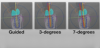
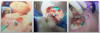
In terms of the clinical relevance of guided surgery, a meta- analysis by Abdelhay et al found that implant failure rates were three times higher with freehand surgery than with guided surgery (6.42% versus 2.25%).5 Figure 2 shows dynamic navigation versus freehand surgery in terms of their different measures. The left-hand panel shows the guided surgery optimal plan; the middle panel shows the expected and acceptable 3° of angular deviation that is achieved using dynamic navigation, with the screw access hole still in the middle of the implant, whereas the right-hand panel shows an expected and unacceptable 7° of deviation using freehand surgery-in many cases bringing the screw access hole right out through a cusp.35
Because dynamic navigation ensures improved accuracy of implant placement, it helps avoid complications of incorrect placement, including fractured implants, decreased efficiency and increased cost from increased prosthetic complexity, peri-implantitis, and late implant loss. Dynamic navigation also helps prevent caries and/or damage to adjacent teeth, and damage to adjacent anatomy, nerves, and blood vessels. A study by Smith et al looked at the incidences of caries related to the distance of the implants from adjacent teeth.36 At approximately 2 mm to 4 mm from the adjacent tooth, there is a corresponding and very large increase in the caries rate because of food impaction, which accurate implant placement can help prevent.
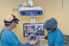
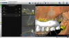
Dynamic navigation also can help with ergonomics. Dynamic navigation allows the practitioner to view the procedure on an elevated heads-up display, which helps avoid twisting of the neck and spine as well as other postural problem (Figure 3).
Dynamic navigation has some challenges, most of which relate to training. Optical interference is the most obvious of such challenges, as the practitioner and the clinical staff must learn to work around the tracking arrays. If an assistant's head obstructs the camera, the system will stop tracking. In order for a surgical team to gain proficiency in performing dynamic-guided navigational surgery, the team must perform between 10 and 20 implant placements.35Once a team has become proficient in dynamic navigation, their accuracy and precision will be statistically equivalent to that seen with any form of computer-assisted surgery.37 In order to gain this level of proficiency, the team should start with simple single- and two-tooth cases before moving on to more complex cases. Every implant is statistically equivalent; thus there are no "easy" cases. In the author's opinion, every implant should be guided by some form of computer-assisted surgery.
WORKFLOW FOR DYNAMIC NAVIGATION
Treatment Planning
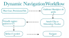
The workflow for dynamic-guided navigational implant surgery (Figure 4) begins with a preoperative examination and imaging utilizing an intraoral scanner and CBCT. The CBCT can be taken with or without fiducial markers. In most dentate cases, a small thermoplastic clip is prepared by the staff and placed in the patient's mouth during the CBCT. This clip automates the registration process.
A variety of digital planning platforms are available (eg, Nobel DTX Studio™, Nobel Biocare; Implant Studio, 3Shape; exoplan, exocad; and CoDiagnostiX®; Dental Wings GmbH). It is important to have a prosthetic digital platform to plan cases. A meta- analysis by Bover-Ramos et al discusses the safety margins for treatment planning: an angular deviation of 4.7°, horizontal coronal deviation of 1.3 mm, horizontal apical deviation of 1.7 mm, and vertical deviation of 1 mm.31 All of these measurements fall within the 95% confidence interval.31 If the practitioner stays within these parameters in treatment planning, correct implant placement should be ensured. After planning, provisionals can then be fabricated using the above-mentioned navigation software or one of the other prosthetic planning software platforms by exporting the plan and either printing or milling provisionals. Digital dentures can be planned and milled for analog pickup. The software allows the practitioner to import the patient's records digitally, plan the dentures, and then mill them from a mono- lithic polymethyl methacrylate (PMMA) puck. The teeth are part of the puck and emerge as the denture is milled. This monolithic design is stronger than a conventional denture, as the entire volume is one piece.
Surgery
Preoperative calibration of the handpieces (45°, 90°, and straight handpieces) and a registration probe is the first step. This is done by the staff.
Registration is the next step in the surgical workflow. For dentate cases, a thermoplastic clip (Figure 5), which has defined reference markers (fiducials), is attached to the patient intraorally during the CBCT. The software finds the clip when the CBCT is uploaded into the planning software and places an .stl file in the position in which it was placed while the CBCT was taken. During calibration, the staff calibrates this clip with a patient tracking array attached by placing the clip with the attached tracking array in front of the camera. This automatically registers the patient to the tracking system. All registrations take a couple of seconds to perform, typically less than 1 minute in total.
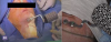
For patients who are edentulous or who did not have the fidu- cials placed for the CBCT, anatomic registration can be used. Using anatomic registration, the patient's own anatomy is used to fuse the "virtual world" to the "real world" to register the system. Figure 6 illustrates the anatomic reference window using a dual scan technique. First, a patient tracking array must be attached to the patient. Whereas in dentate patients a thermoplastic clip is used as described above, in edentulous patients the patient tracking array must be attached to the jaw that is to be tracked. The tracking array can be attached using screws with arms or a plate using screws (Figure 7). The patient is registered when the practitioner touches the points that he or she has selected on the CT with a probe in front of the camera. The practitioner is now ready to navigate.
Once the patient is registered, a "system check" should be performed to ensure the tracking system is accurately registered. To do this, the surgeon or staff touches a spot on the patient with the drill and looks at the monitor. If the image on the monitor matches the position in the mouth, the system is tracking accurately. Any deviations can now be "refined" using the tracking software. This software tool allows the practitioner to use the patient's anatomy to refine the registration and to correct the change of clip position. With the use of anatomic registration, the practitioner can utilize any CT, including smaller field-of-view CTs, and the need for fiducials in the mouth is eliminated. Because the practitioner does not need fiducials or markers in the CT at the time that the CT is obtained, the procedure is enabled to be minimally invasive, even for edentulous cases. No rescan with a clip of edentulous screws is needed, and there are more immediate provisional opportunities.
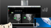
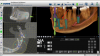
Next, the drilling and placement of the implants are performed as the practitioner views the computer monitor for real-time information on the position of the drill (Figure 8). Violet light is emitted from the camera array. It strikes the tracking arrays, and their position is captured by the cameras. Because all but violet light is filtered out by the system, dental lights and head lights do not affect tracking. As mentioned earlier, one of the challenges of navigational surgery is learning how to avoid getting in the way of the light. If the practitioner or staff blocks the light, tracking stops; this is known as optical interference. The tracking software that is used is extremely important. The target should show all six degrees of freedom in one view; as shown in Figure 8, the tip of the drill is the blue dot, the top of the drill is the green donut, and the outside green ring indicates the depth. It progressively changes from yellow to green (within 1 mm of the ideal depth) to red (when the ideal depth is exceeded). During surgery, the surgeon watches the monitor and the staff watches the patient to ensure proper retraction of soft tissue. This heads-up position allows for a comfortable and ergonomically safe head posture for the team.
The workflow for all forms of computer-assisted surgery involves more steps than for freehand surgery. The only way to increase efficiency is to have the staff perform as many of the imaging, initial planning, calibration, and registration steps as possible, while the practitioner only approves the plan and guides the procedure. In this way, the surgery will be performed more efficiently than with freehand techniques, as the surgeon will have more accessible information and greater confidence that the implants will be placed accurately. Compared with static guides, navigation is more efficient and flexible, as no objects need to be fabricated and the plan can be changed at any time.11,38
The last link in the complete digital workflow is the final impression. For single- to three-unit restorations, intraoral laser scans can be taken with predictable accuracy. For larger restorations, photogrammetry or navigated photogrammetry must be used if an accurate impression is to be taken. After the implants are placed, scan bodies are placed on the implants (Figure 9). The cameras of the navigation system are then used to capture the implant positions. Because the tracking array is on the patient, this impression is related to the entire plan and all of the images are used, as they are all in the same coordinate system (Figure 9).
Clinical Examples
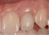
Figure 10 shows a classic high-risk esthetic case. A 19-year-old female patient with a thin gingival biotype presented with a congenitally missing tooth No. 10. She had previously undergone clear aligner therapy to improve the esthetics of her teeth to the extent possible. The clinician discussed options with her: a bonded Maryland Bridge, a three-unit fixed prosthesis, or implant placement. The patient desired a dental implant with an immediate provisional. It was decided that placement of an implant would require a hybrid workflow-ie, analog technology as well as digital technology using dynamic navigation. Figure 11 shows an imaging guide that can be used in such a case, as well as a virtual tooth.
To measure accuracy, the clinician superimposed the plan on the postoperative CT scan and then measured the difference with software. This case had an angular deviation of 3.1°, a platform deviation of 0.81 mm, and an apical deviation of 0.45 mm-all of which were within acceptable parameters.
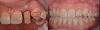
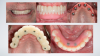
Figure 12 shows the temporary abutment (left panel) after the implant and connective tissue graft were placed, and the patient 2 weeks postoperatively (right panel). Seven years later, the restoration remains sound (Figure 13).
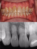
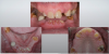
Figure 14 through Figure 18 show a partially dentate patient for whom a fully digital workflow was utilized. This 47-year-old male presented with root blunting and mobility of teeth Nos. 7, 8, and 9 (Figure 14). A thermoplastic clip was attached during the CBCT, and an intraoral scan was taken and superimposed on the CBCT. The case was then planned in the navigation planning software (Figure 15). Once the teeth were extracted, intraoral scanning was performed. The intraoral scan was imported into lab software (Figure 16), and a PMMA milled screw-retained prosthesis was fabricated. The prosthesis was placed the next morning (Figure 17). Two months later, a new intraoral scan was taken to capture the mature soft tissue, and the final milled titanium abutment and restoration were delivered (Figure 18).
WORKFLOW FOR FULL-ARCH RECONSTRUCTIONS
The workflow for full-arch reconstructions is as follows: implant planning, fabrication of the provisional restorations, calibration of the surgical instruments, attachment of the edentulous tracker to the patient, virtual registration, refinement of the registration if necessary, and implant placement.
Treatment Planning
The workflow for planning full-arch reconstructions with dynamic navigation includes the following:
• Planning implant position
• Planning bone reduction
• Planning position of fixation screws
• Selecting anatomic registration points
Planning Implant Position
The position of the implants must be prosthetically driven. Any of the major software planning tools can be used with dynamic navi- gation. The software included with the navigation system allows for dual scan planning, as dual scan images are suitable for this prosthetically driven approach. Once the plan is completed, the data should be sent for fabrication of the provisionals. If navigation software is used for implant planning, the data can be exported as individual or linked generic .stl files, or if planning is done without the navigation software, the data can be imported into the navigation system.
Planning Bone Reduction
For implant planning, bone reduction should be done using small preps-1-mm rods placed just above the level of the platforms (Figure 19). During surgery, the entry points of the preps are used to mark the reduction height using navigation. A navigated straight or 45º handpiece is then used to connect the points and complete the osteotomy, using navigation to ensure that the lingual or palatal soft tissue is not perforated.
Planning Position of Fixation Screws
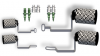
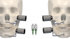
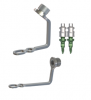
The key to performing dynamic navigational implant surgery in an edentulous patient is to have an easy way to attach the tracking device. Figure 20 shows the minimally invasive intraoral screws and arms used to hold the patient tracking array. Ideal anatomic locations are the front of the mouth; in the mandible, the symphysis region; and in the maxilla, the nasal spine and piriform rim regions, which are often sites of excellent cortical bone. These screws can be oriented either horizontally or vertically. The navigation software has virtual images of the fixation screws and arms for easy selection and visualization of the sites. For those situations requiring extraoral fixation (eg, minimal mouth opening in patients with scleroderma or other limiting factors), the inferior border of the mandible or zygomatic buttress can be planned (Figure 21).
Selecting Anatomic Registration Points
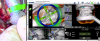
The last step before surgery is the selection of the anatomic locations that will be used for anatomic registration. Superimposed intraoral scans and artificial intelligence enhanced-segmented images are extremely useful for this step, as the .stl files do not have radiographic artifacts (Figure 22).
Surgery
The workflow for implant surgery is as follows:
• Calibration
• Placing the patient tracking array
• Registration and refinement
• Navigation of bone reduction and implants
Calibration
Ideally, the staff will calibrate the drills and the registration probe. Two drills and the probe can be calibrated. A straight handpiece or 45° handpiece is calibrated for guided bone reduction.
Placing the Patient Tracking Array
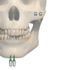
This is the only step that is unique to the full-arch or edentulous reconstruction workflow. To attach the tracking device, incision design must be planned first. Stab incisions are indicated if minimal bone reduction is planned, but if extensive bone reduction is necessary, a crestal incision should be used (Figure 23). In the maxilla, start with a vertical incision in the midline to find the nasal spine. The bone is usually dense in this area. Next, the screws are placed, the arm is placed on the shoulder of the screw, and a nut is used to tighten down the arm with a driver. Extraoral locations can be used for patients with minimal mouth opening or poor bone volume and quality. In Figure 24, the patient shown in the left-hand panel had scleroderma and could open her mouth only 10 mm to 12 mm. A stab incision was used at the inferior border of the mandible. When there is minimal mouth opening, as in this case, the patient cannot undergo implant surgery using a static guide, but can be treated with surgery guided by dynamic navigation. The patient shown in the right-hand panel of Figure 24 had traumatic maxillofacial injuries and poor-quality bone that necessitated a complete maxillary reconstruction. In this patient, a stab incision was created over the zygomatic buttress. In the author's experience, extraoral fixation is useful for patients with an extremely atrophic maxilla or who have lost ana- tomic structures secondary to resections, and for auricular implant placement. Extraoral fixation is also useful for off-label use cases, such as zygoma implants, osteotomies, and patients requiring resections and reconstructions. The author recommends the extraoral parts shown in Figure 25.
Registration and Refinement
Once the patient tracking array is placed, registration and refinement are carried out as previously described for dentate patients. For edentulous patients, anatomic points such as the mental fora- men and other bony landmarks can be used. If extraction of any teeth is planned, these teeth can be used for this step before extraction, provided that they are not mobile. The bony contours of the mandible and maxilla can be used for refinement. In the author's experience, placing the patient tracker and performing the registration typically takes 10 minutes.
Navigation of Bone Reduction and Implants
The drills are then measured and, if necessary, bone reduction is accomplished using the prep to determine the height and the guided straight handpiece to determine the depth. With dynamic navigation, unlike static guides, all bone reduction does not need to be accomplished at once, and can be done one quadrant at a time. Once the implants have been placed, the tracking array is removed.
Clinical Example
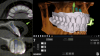
Figure 26 shows a full-arch classic "All-on-X" case at presentation. The patient was a 66-year-old male with a mutilated dentition. The patient had lost vertical dimension and desired a fixed restoration. Options were discussed with the patient, including dentures, which the patient refused long term. The patient instead agreed to a plan to undergo extractions of his remaining dentition and have an immediate maxillary denture with five mandibular implants and an immediate mandibular hybrid denture. The practitioner worked with a laboratory that could provide a monolithic PMMA digitally milled denture. Two months following implant treatment of the mandibular arch, the patient had six maxillary implants placed with immediate denture conversion.
The workflow presented is a hybrid analog and digital approach.
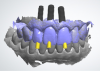
Intra- and extraoral photographs, intraoral scans, and analog impressions were taken and a CBCT was acquired. A digital smile design was accomplished and records sent to the laboratory (Figure 27). The digital records and analog models were scanned and imported into the digital denture scanning software that was used to plan the denture. The denture plan was then imported into the implant planning software (Nobel DTX Studio™, Nobel Biocare; alternatively: X-Guide, X-Nav Technologies; Implant Studio, 3Shape) to create the plan for the implants (Figure 28). Next, the plan was imported into the navigation software system of the navigation unit, and the practitioner was able to begin planning bone reduction and screw positions.
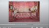
At the time of surgery, the maxillary dentition was removed, bone grafts were placed, and an immediate denture was relined in the predetermined occlusion using an occlusal stent. Next, a crestal incision was made in the mandible. The fixation screws were then placed below the level of the planned bone reduction. The tracker arm was placed on the platform of the screws and the nuts tightened to rigidly fixate the patient tracking arm. The tracker array was then tightened into place. The arm of the tracking array additionally assists as it retracts the lip. Next, the patient was registered anatomically by touching the teeth in the predetermined locations. A system check was performed to verify the accuracy of the tracking system. No refinement was necessary. Bone reduction was then accomplished using a straight handpiece under navigation, and the implants were placed. The prosthodontist then used temporary cylinders and picked up the positions of the implants using the milled mandibular transition appliance. The occlusal locks at the distal of the prosthesis assured that the correct vertical dimension was obtained (Fig- ure 29). The incision was closed, and the denture was finished in the laboratory and delivered the next morning.
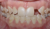
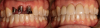
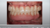
The hybrid denture was delivered the next day. After 2 months, the patient was seen again, and the practitioner performed osteo- tomies and placed six maxillary implants. Figure 30 is a retracted view of the patient's dentition 1 week postoperatively. For both the mandible and maxilla together, the mean angular deviation was 2.08 (SD, 0.85), the mean platform deviation was 0.97 mm (SD, 0.43), and the mean apical deviation was 1.25 mm (SD, 0.44), which is within the expected range. With the help of dynamic navigation, the procedure was extremely successful. Figure 31 shows the patient's digitally milled PMMA prosthesis and soft tissue at 1 year postoperatively.
CONCLUSION
Dynamic navigation is not a single technique, but rather is a mode of surgery that is useful for multiple procedures, and thus is not limited to implant placement. It is important to note that, while there is a learning curve, proficiency can usually be achieved after 10 to 20 implant placements.35 Dynamic navigation is appropriate for any procedure in which the practitioner desires improved vision with magnification of anatomic locations (in complex three dimensions) requiring micron accuracy. The improved accuracy of dynamic navigation, equivalent to that of static- guided and robotic surgery but with enhanced vision and greater flexibility, ultimately has been found to offer improved predictability and enhanced clinical outcomes.
REFERENCES
1. Sun T-M, Lee H-E, Lan T-H. Comparing accuracy of implant installation with a navigation system (NS), a laboratory guide (LG), NS with LG, and freehand drilling. Int J Environ Res Public Health. 2020;17(6):2107. 2. Block MS, Emery RW, Lank K, Ryan J. Implant placement accuracy using dynamic navigation. Int J Oral Maxillofac Implants. 2017;32(1):92-99.
3. Para-Tresserra A, Marques-Guasch J, Orte ga-Martinez J, Basilio-Monne J, Hernandez-Alfaro F. Current state of dynamic surgery. A literature review. Med Oral Pathol Oral Cir Bucal. 2021;26(5): e576-e581.
4. Dioguardi M, Spirito F, Quarta C, et al. Guided dental implant surgery: systematic review. J Clin Med. 2023;12(4):1490.
5. Abdelhay N, Prasad S, Gibson MP. Failure rates associated with guided versus non-guided dental implant placement: a systematic review and meta-analysis. BDJ Open. 2021;7(1):31.
6. Sigcho López DA, García I, Da Silva Salomao G, Cruz Laganá D. Potential deviation factors affecting stereolithographic surgical guides: a systematic review. Implant Dent. 2019;28(1):68-73.
7. Unsal GS, Turkyilmaz I, Lakhia S. Advantages and limitations of implant surgery with CAD/CAM surgical guides: a literature review. J Clin Exp Dent. 2020;12(4):e409-e417.
8. Eu D, Daly MJ, Irish JC. Imaging-based navigation technologies in head and neck surgery. Curr Opin Otolaryngol Head Neck Surg. 2021;29(2):149-155.
9. Block MS, Emery RW. Static or dynamic navigation for implant placement-choosing the method of guidance. J Oral Maxillofac Surg.2016;74(2):269-277.
10. Panchal N, Mahmood L, Retana A, Emery R 3rd. Dynamic navigation for dental implant surgery. Oral Maxillofac Surg Clin North Am. 2019;31(4):539-547.
11. Pellegrino G, Bellini P, Cavallini PF, et al. Dynamic navigation in dental implantology: the influence of surgical experience on implant placement accuracy and operating time. An in vitro study. Int J Environ Res Public Health. 2020;17(6):2153.
12. Campbell A, Costello BJ. Retrieval of a displaced third molar using navigation and active image guidance. J Oral Maxillofac Surg. 2010;68(2):480-485.
13. Lübbers H-T, Obwegeser JA, Matthews F, Eyrich G, Grätz KW, Kruse A. A simple and flexible concept for computer-navigated surgery of the mandible. J Oral Maxillofac Surg. 2011;69(3):924-930.
14. Gerbino G, Zavattero E, Berrone M, Berrone S. Management of needle breakage using intraoperative navigation following inferior alveolar nerve block. J Oral Maxillofac Surg. 2013;71(11):1819-1824.
15. Wang J, Cui N-H, Guo Y-J, Zhang W. Navigation-guided extraction of impacted supernumerary teeth: a case report. J Oral Maxillofac Surg. 2017;75(6):1136.e1-1136.e5.
16. Lotz M, Schumacher C, Stadlinger B, Ikenberg K, Rücker M, Valdec S. Accuracy of guided biopsy of the jawbone in a clinical setting : a retrospective analysis. J Craniomaxillofac Surg. 2021;49(7): 556-561.
17. Magic M, Wang F, Fan S, Wu Y. Dynamic navigation guidance for bone reduction in maxilla: case report. Int J Oral Maxillofac Implants. 2021;36(1):e1-e6.
18. Stefanelli LV, Pranno N, Angelis F De, Rosa S La, Polimeni A, Di Carlo S. Navigated antral bone expansion (NABE): a prospective study on 35 patients with 4 months of follow-up post implant loading. BMC Oral Health. 2020;20(1):273:1-12.
19. Chen Y-T, Chiu Y-W, Peng C-Y. Preservation of inferior alveolar nerve using the dynamic dental implant navigation system. J Oral Maxillofac Surg. 2020;78(5):678-679.
20. Lotz M, Schumacher C, Stadlinger B, Ikenberg K, Rücker M, Valdec S. Accuracy of guided biopsy of the jawbone in a clinical setting: a retrospective analysis. J Craniomaxillofac Surg. 2021;49(7): 556-561.
21. Meng T, Zhang X. Accuracy of intentionally tilted implant placement in the maxilla using dynamic navigation: a retrospective clinical analysis. Int J Oral Maxillofac Surg. 2022;51(4):552-557.
22. Wang F, Bornstein MM, Hung K, et al. Application of real-time surgical navigation for zygomatic implant insertion in patients with severely atrophic maxilla. J Oral Maxillofac Surg. 2018;76(1):80-87.
23. Badiali G, Roncari A, Bianchi A, Taddei F, Marchetti C, Schileo E. Navigation in orthognathic surgery: 3d accuracy. Facial Plast Surg.2015;31(5):463-473.
24. Emery RW, Korj O, Agarwal R. A review of in-office dynamic image navigation for extraction of complex mandibular third molars. J Oral Maxillofac Surg.2017;75(8):1591-1600.
25. Retana A, Emery RW, Keir V. Removal of impacted supernumerary teeth using a dynamic surgical navigation system: a case report. J Oral Maxillofac Surg.2019;77(6):1130-1134.
26. Dianat O, Nosrat A, Mostoufi B, Price JB, Gupta S, Martinho FC. Accuracy and efficiency of guided root-end resection using a dynamic navigation system; a human cadaver study. Int Endod J.2021;54(5)793-801.
27. Dianat O, Nosrat A, Tordik PA, et al. Accuracy and efficiency of a dynamic navigation system for locating calcified canals. J Endod.2020;46(11):1719-1725.
28. Pellegrino G, Ferri A, Del Fabbro M, Prati C, Gandolfi MG, Marchetti C. Dynamic navigation in implant dentistry: a systematic review and meta-analysis. Int J Oral Maxillofac Implants. 2021;36(5): e121-e140.
29. Wei S-M, Zhu Y, Wei JX, Zhang C-N, Shi J-Y, Lai H-C. Accuracy of dynamic navigation in implant surgery: a systematic review and meta-analysis. Clin Oral Implants Res. 2021;32(4):383-393.
30. Stefanelli LV, DeGroot BS, Lipton DI, Mandelaris GA. Accuracy of a dynamic dental implant navigation system in a private practice. Int J Oral Maxillofac Implants. 2019;34(1):205-213.
31. Bover-Ramos F, Viña-Almunia J, Cervera-Ballester J, Peñarrocha- Diago M, García-Mira B. Accuracy of implant placement with computer-guided surgery: a systematic review and meta-analysis comparing cadaver, clinical, and in vitro studies. Int J Oral Maxillofac Implants. 2018;33(1):101-115.
32. Raico Gallardo YN, da Silva-Olivio IRT, Mukai E, Morimoto S, Sesma N, Cordaro L. Accuracy comparison of guided surgery for dental implants according to the tissue of support: a systematic review and meta-analysis. Clin Oral Implants Res. 2017;28(5):602-612.
33. Cassetta M, Stefanelli LV, Giansanti M, Di Mambro A, Calasso S. Accuracy of a computer-aided implant surgical technique. Int J Periodontics Restorative Dent. 2013;33(3):317-325.
34. Block MS, Emery RW, Lank K RJ. Accuracy using dynamic navigation. Int J Oral Maxillofac Implants. 2017;32:92.
35. Block M, Emery RW, Lank K, Ryan J. Implant placement accuracy using dynamic navigation. J Oral Maxillofac Implants.2017;32(1): 92-99.
36. Smith R, Rawdin SB, Kagan V. Influence of implant-tooth proximity on incidence of caries in teeth adjacent to implants in molar sites: a retrospective radiographic analysis of 300 consecutive implants. Compend Contin Educ Dent.2020;41(1):e1-e5.
37. Block MS, Emery RW, Cullum DR, Sheikh A. Implant placement is more accurate using dynamic navigation. J Oral Maxillofac Surg. 2017;75(7):1377-1386.
38. Wang X, Shaheen E, Shujaat S, et al. Influence of experience on dental implant placement: an in vitro comparison of freehand, static guided and dynamic navigation approaches. Int J Implant Dent. 2022;8(1):42.