You must be signed in to read the rest of this article.
Registration on CDEWorld is free. Sign up today!
Forgot your password? Click Here!
There are a number of factors involved in achieving a successful outcome for an implant-supported prosthesis. Quality and quantity of the bone, experience level of the operator, and the type and design of the final restoration all play an important part in the long-term success of the implant. Another major factor is the placement of the implant fixture in a bucco-lingual, mesio-distal, and apico-coronal dimension.1 The esthetics and function of the final restoration are strongly affected by on the placement of the implant fixture. A minimal amount of offset of the optimal location of the implant fixture can create a host of problems for the surgeon, the restoring clinician, as well as the laboratory technician. Rarely, it seems that the misplaced implant fixtures are surgically corrected (removal and subsequent replacement). Then the chain of blame begins. Ultimately, the dental technician has to devise a compromised restoration. In the end, the patient is the one who suffers the most.
Preventing the Initial Problem
The use of a surgical guide, which is fabricated from a diagnostic mock-up, is considered to be protocol in the placement of dental implants. The guide can dictate the drilling position and angulation.2 The literature describes a number of different types of guides.3-8 The rate of prosthetic success diminishes when the use of a surgical guide is abandoned and the operator chooses to visually place the implant.
There are certain criteria when fabricating a surgical guide. Ideally, when the guide is placed intraorally, it must be stable and accessible. It should have the ability to be sterilized and reused for a number of procedures on that individual patient.9 A radiopaque marker placed in the implant site is very helpful in locating the guide if diagnostic imaging is to be used and is helpful in orientation of the proposed implant sites to vital anatomical structures (eg, IAN, maxillary sinus).10 Periapical, panoramic, and tomographic radiographs have been used in the past. Presently, verification with either CT scans or cone-beam imaging can be used more accurately for intraoral placement, as this allows 3-D orientation which is lacking in traditional radiographs.11 An incorrect position requires fabrication of a new surgical guide but will prevent complications for the restorative team.
The diagnostic mock-up should represent the final restoration in an ideal position in all dimensions. For example, the gingival flange on the surgical guide should represent the intended gingival margin of the restoration. This will allow the operator a reference point if there is any alteration to the bucco-lingual position depending on the width of the alveolar ridge.
Stumpel8 categorized the concepts of surgical guide design into three categories. The first is a non-limiting design that designates to the surgeon an indication as to the space the final restoration should occupy. This design allows the most dimensional variability in the implant fixture location. The second category is a partial-limiting design that incorporates a metal guide sleeve for the pilot drill in the surgical guide. This allows for the proper angulation of the pilot drill only. There are different sized inserts that can be placed in the guide sleeve which accommodate the different diameter drills. The subsequent osteotomy is then finished without the use of the surgical guide. The last category is the complete-limiting design that restricts the position, angulation, and depth of all the instruments used for the osteotomy. This last design category restricts any variation by the surgeon. It also requires the most preoperative radiographic and clinical data.
Surgical Guide Materials
Materials for fabrication of the surgical guide can be rigid, flexible, or a combination of both. Traditionally, acrylic (heat- and cold-cure) and thermal vacuum-form material have been the material of choice and is usually fabricated in the dental laboratory. A recently introduced clear polyvinyl material (SHARP™, Parkell) can also be used. The simplicity in creating a surgical guide with this material allows the clinician to complete the fabrication in the dental office. This material can be used solely or in combination with a rigid plastic.
Additional materials that can be integrated into the surgical guides are metal, ceramic, and Delrin plastic drill-guide assemblies that are supplied by several manufacturers, such as Guide Right™ and Basic Dental Implants. The drill guide inserts can be incorporated in the partial and completely limited surgical-guide versions.
Examples of Surgical Guides
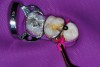
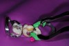
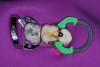
The first example shows a traditional method using denture teeth and heat-cure acrylic to fabricate a non-limiting surgical guide. First, the denture teeth are set in the edentulous space on a mounted cast (Figure 1 through Figure 3). The teeth are set into the position that represents the final restoration. Once the occlusion is verified, wax is added along the incisal edges (above the height of contour) of the adjacent teeth and continues to the opposite side of the arch. This extension of the surgical guide provides cross-arch stability. The cast is removed from the mounting and invested in a denture flask using the usual laboratory steps in denture fabrication. The flask is then separated; the denture teeth and wax are removed with boiling water. Clear acrylic is mixed and then packed into the flask and heat-cured. After deflasking, the surgical guide is trimmed, finished, and polished (Figure 4 through Figure 6). Any undercut areas on the proximal sides of the adjacent teeth are removed to facilitate seating of the appliance during the surgical procedure. The appropriate size holes that correspond to the sized surgical drills are placed through the center of the teeth.
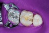
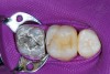
The fabrication of a non-limiting surgical guide can easily be completed in the dental office using the clear polyvinyl material. The stone casts are first mounted. Denture teeth are then set into the edentulous space. For the typical dental office, denture teeth are probably not an ordinary stocked item. An alternative to using denture teeth is to use old composite restorative material and create the desired restoration in the edentulous space. Occlusal anatomy is not critical when fabricating a composite tooth on the cast, and the goal is to fabricate a tooth shape that has the proper mesio-distal and bucco-lingual dimensions of the prosthetic tooth that will ideally fill the space. A separating medium, such as dry silicone spray or tin-foil substitute, is first applied to the edentulous space and the adjacent proximal surfaces. The restoration is then created incrementally using the old composite while light-curing the layers as they are applied (Figure 7 and Figure 8). Severe undercuts on the proximal, palatal, and lingual aspects of the adjacent teeth are blocked out.
At this point, the clinician has two options. One option is to remove the stone cast from the mounting and fabricate a rigid (0.04 to 0.08 inches) thermal vacuum-forming stent over the entire model (Figure 9). Drill guide holes are then placed in the center fossa of the intended restoration. Cutting above the height of contour, the stent is removed from the cast. The composite mock-up restoration is also removed from the model or, if it is attached to the vacuum-form stent, then it is removed, creating a void in the edentulous space.
The other option, in lieu of using the vacuum-form material, is to apply the clear polyvinyl material over all of the teeth on the stone cast, including the composite mock-up. When using this material it is essential to first remove the oxygen-inhibited layer that remains on the entire composite mock-up with alcohol. This will prevent any interference in the condensation reaction of the polyvinyl material. The material can be placed below the height of contour, which will provide retention of the surgical guide during the surgical phase (Figure 10). The same steps apply as described for the first option. The drill guide hole is placed through the central fossa of the prosthetic mock-up and then the surgical guide is removed from the model. The mock-up restoration is also removed from the model.
The remaining steps are similar for either option at this point. Both appliances are relined in the prosthetic mock-up area with the clear polyvinyl material. For the vacuum-forming stent, a layer of polyvinyl tray adhesive is applied to the undersurface area of the prosthetic mock-up (Figure 11). A small amount of clear polyvinyl material is loaded into the mock-up area and the stent is fitted back on the stone cast. Excess material can flow out through the drill hole on the occlusal surface and out through the gingival margin area. After the clear polyvinyl material sets, the drill hole can be re-established (Figure 12).
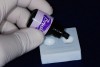
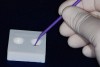
As for the clear polyvinyl surgical guide, application of the tray adhesive is not necessary. The clear polyvinyl material is injected into the impressed area created by the prosthetic mock-up and the guide is placed back on the stone cast (Figure 13). During this relining step, the excess material extrudes through the drill hole and the gingival margin area. An option of incorporating a radiographic marker (a small piece of lead foil from an x-ray film packet) into the surgical guide can be placed before injecting the clear polyvinyl material. After the material sets, the drill hole is re-established with the same drill used earlier and the surgical guide can now be removed from the model (Figure 14). The second application of the clear polyvinyl material lengthens the walls of the drill hole by creating more surface area to control the path of the drill. It also engages the undercut areas of the proximal walls of the adjacent teeth. When the guide is placed, the elasticity of the clear polyvinyl material can lock into the undercut areas of the adjacent teeth creating more retention and stability of the surgical guide.
The partial-limiting surgical guide, as previously mentioned, incorporates a commercially manufactured metal, ceramic, or Delrin plastic sleeve and corresponding drill. It can be constructed with acrylic or the clear polyvinyl material. The sleeves have a retaining bracket that allows for either material to “lock on” for stable retention. Ceramic sleeves are indicated when cone-beam radiography is anticipated in the verification step as opposed to conventional radiographic techniques (periapical and panoramic radiographs). The ceramic material minimizes the x-ray scatter produced by the metal versions.
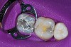
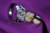
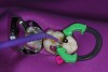
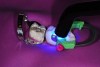
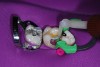
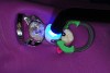
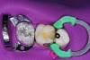
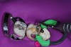
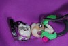
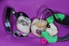
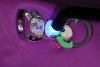
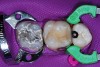
The following example illustrates the use a ceramic sleeve with the clear polyvinyl material. These steps are also used when using a metal sleeve assembly. As previously mentioned, severe undercuts on the proximal, palatal, and lingual aspects of the adjacent teeth are blocked out. Spraying the model with a dry silicone spray will facilitate the removal of the finished surgical guide. After the denture tooth or composite mock-up restoration is secured in the edentulous space, a 3/32” drill hole is placed through the restoration and into the stone cast (Figure 15). The restoration is then removed from the cast and the 3/32” drill hole is extended 10 mm deep into the stone cast (Figure 16). A 3-mm straight guidepost is then placed into the hole. The angulation of the guidepost will provide the trajectory of the osteotomy drill. A fabrication insert is placed into a 5.3-mm guide sleeve and together they are positioned onto the 3-mm guidepost. The guide sleeve has a retention bracket that is positioned facing the lingual or palatal side (Figure 17). The clear polyvinyl material is then injected around the guide sleeve assembly and the adjacent teeth (Figure 18). The fabrication insert and the straight guidepost are removed. The surgical guide now can be removed from the stone cast.
Intraoral verification of the proposed implant position and orientation can be accomplished prior to initiating surgery using a radiograph with the surgical guide in place. Place the surgical guide in the patient’s mouth and take a periapical or panoramic radiograph. On the radiograph, lines can be drawn parallel to the sides of the guide sleeve to predict the projection of the long axis of the implant fixture. If the projection of the long axis is not satisfactory, for example, the drawn lines on the radiograph tend to encroach on the apical area of one of the adjacent teeth, then the surgical sleeve can be removed from the surgical guide and repositioned. This step, if necessary, can be easily completed when using the clear polyvinyl material. On the stone cast, replace the mock-up restoration and place the drill tip in the same access hole but change the angulation either to the mesial or distal depending on what is required. Repeat the steps previously mentioned. Again, take the surgical guide to the patient and obtain another radiograph. Then check the projection of the long axis by drawing the lines. Although this verification step might require more chair time in repositioning the guide sleeve, it involves little time compared to the complications that may arise with a misplaced implant fixture.
Whatever material is used to fabricate the surgical guide it is essential that the appliance soak in a 2% to 4% glutaraldehyde solution for at least 30 minutes for disinfection purposes.12
Conclusion
The most difficult and critical step in implant dentistry is the correct positioning of the implant fixture in the bone and its spatial relation to the adjacent teeth. The use of surgical guides has made this discipline more predictable. There are a number of techniques and materials that have been proposed in the fabrication of surgical guides. Many of these fabrication techniques have been completed in the dental laboratory. The introduction of a clear polyvinyl material allows the clinician to construct a surgical guide in the dental office. The material allows to easily change position of a drill guide sleeve when used.
Acknowledgment
Special thanks to Ruth Egli, RDH, for her editorial contribution.
References
1. Greenstein G, Cavallaro J. The relationship between biological concepts and fabrication of surgical guides for dental implant placement. Compend Contin Edu Dent. 2007;28(4):196-204.
2. Jalbout Z, Tabourain G, eds. Glossary of Implant Dentistry II. International Congress of Oral Implantologists; Upper Monclair, NJ. 2008;84.
3. Kim JY. The implant positioning guide and the “stent.” Dent Implantol Update. July 2009.
4. Almog DM, Torrado E, Meitner SW. Fabrication of imaging and surgical guides for dental implants. J Prosthet Dent. 2001;85:504-508.
5. Burns DR, Crabtree DG, Bell DH. Template for positioning and angulation of intraosseous implants. J Prosthet Dent. 1988;60:479-483.
6. Higginbottom FL, Wilson TG. Three-dimensional templates for placement of root-form dental implants: a technical note. Int J Oral Maxillofac Implants. 1996;11:787-793.
7. Meitner SW, Tallents RH. Surgical templates for prosthetically guided implant placement. J Prosthet Dent. 2004;92:569-574.
8. Stumpel LJ III. Cast-based guided implant placement: A novel technique. J Prosthet Dent. 2008;100:61-69.
9. Greenstein G, Cavallaro J. The relationship between biological concepts and fabrication of surgical guides for dental implant placement. Compend Contin Edu Dent. 2007;28(4):196-204.
10. Siciha A, Enrile FJ, Buitrago P, et al. Evaluation of the precision obtained with a fixed surgical template in the placement of implants for rehabilitation of the completely edentulous maxilla: a clinical report. Int J Oral Maxillfac Implants. 2000;15:272-277.
11. Meitner SW. Fabrication and evaluation of ceramic template components for precision implant placement. Inside Dentistry. In press.
12. Kugel G, Perry RD, Ferrari M, Lalicata P. Disinfection and communication practices: A survey of U.S. dental laboratories. J Am Dent Assoc. 2000;131(6):786-792.
About the Author
Gregg A. Helvey, DDS, Adjunct Associate Professor, Virginia Commonwealth University School of Dentistry, Richmond, Virginia; Private Practice, Middleburg, Virginia