You must be signed in to read the rest of this article.
Registration on CDEWorld is free. Sign up today!
Forgot your password? Click Here!
During the past 30 years, an emerging technology that encompasses computed tomography (CT), cone-beam computed tomography (CBCT), and interactive treatment-planning software has slowly evolved into a necessary tool for diagnosis, treatment planning, and delivery of dental implant and associated restorative and surgical procedures. The integration of these innovative tools has helped to define new paradigms for appreciating anatomy, improving accuracy, and enhancing presurgical prosthetic planning to achieve true restorative-driven implant dentistry. In the past, the standard tools for diagnosis and treatment planning were two-dimensional (2D) periapical and panoramic imaging.1-4 The dental implant literature is replete with prescripts and determinants for proper placement and angulation, methods to preserve interdental papilla, and implant-to-tooth and implant-to-implant parameters.5-10 However, until recently all documentation was based on 2D radiography or direct clinical examination at the alveolar crest, which could not allow a complete assessment of the patient’s anatomy or spatial position of the implant.
Recent advances in CT and CBCT technology, combined with the evolution of interactive virtual treatment-planning software applications, have empowered clinicians with enhanced diagnostic capabilities for implant receptor-site assessment. These innovative tools have allowed for new paradigms to be developed, which may supersede current methods of presurgical planning for dental implant reconstruction.11-17
Congenitally Missing Laterals
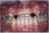
A 17-year-old boy presented with a history of congenitally missing maxillary lateral incisors. The patient had been under the care of an orthodontist for several years to manage his occlusion during his adolescent growth phase. The patient originally presented with his parents after being told that the “braces were ready to be removed, and their son was now ready for implants to replace the missing teeth.” This is not an uncommon circumstance, and unfortunately the orthodontic alignment was performed before the patient was sent to the restoring dentist. Therefore, the orthodontist was not aware of the space requirements for future implant placement. This case highlights the importance of proper communication between all members of the implant team, especially during the orthodontic planning phase. The patient’s medical history was unremarkable, and the patient was found to be healthy and a good potential candidate for dental implants to replace the missing lateral incisors.
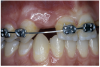
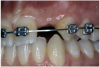
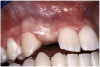
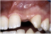
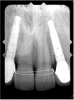
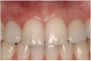
Periapical radiographs were taken to help determine the mesial-distal inclinations of the adjacent tooth roots (Figure 1). The radiographs revealed a serious issue, convergent roots for the right canine and right central, which eliminated that area as a potential implant-receptor site. The space between the left central and canine teeth was minimal, although the roots were relatively parallel. Clinical examination (manual palpation of the root eminences superiorly to the vestibule on the right side) confirmed the root convergence (Figure 2A). The flat, wide zone of the keratinized tissue and lack of interdental papilla was evident for the missing right lateral incisor. There was a marked difference in clinical appearance for the left lateral, which could impact the eventual plan of treatment (Figure 2B). Other significant clinical findings included bilateral facial bone concavities, which existed as a result of the congenitally missing tooth roots. As a diagnostic cue to the underlying bone topography, it is important to follow the demarcation between attached and unattached gingival tissue, and note the crestal width of the available keratinized tissue (Figure 2C).
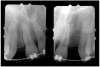
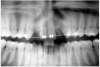
Based upon the intraoral examination and periapical radiographs, additional orthodontic intervention was recommended to move and rotate the roots to gain enough space for implant placement. This information was conveyed to both the parents and to the treating orthodontist. After several additional months, a panoramic radiograph was provided by the orthodontist to evaluate the distance between the clinical crowns and tooth roots (Figure 3). The lack of sharpness, definition, and radiographic artifacts made it impossible to determine whether implants could be successfully placed based on the 2D panoramic image. This diagnostic predicament was discussed with the patient and his parents, and it was suggested that a CT scan would be necessary to accurately assess the bone topography and spatial orientation of the adjacent roots. The parents agreed, and the patient was given a prescription for a CT scan study at a local radiology center.
The universal digital imaging and communication in medicine (DICOM) data was then converted for interpretation, using an interactive treatment-planning software application (SIM/Plant™, Materialise Dental, www.materialise.com). Other software on the market when this article was first written included Virtual Implant Placement (VIP) (Implant Logic System Ltd, www.biohorizons.com), NobelGuide™ (Nobel Biocare USA, LLC, www.nobelbiocare.com), ImplantMaster (iDent, www.ident-surgical.com), Implant 3D (Media Lab, www.mlsw.com), EasyGuide (Keystone Dental Inc, www.keystonedental.com), and Facilitate™ 11 (Astra Tech Inc, www.astratech.us), as well as the CBCT’s preinstalled software. To further define the region of interest and the existing anatomy, it is important to remove extraneous data or scatter caused by highly radiopaque artifacts. For the present example, the process of scatter elimination was accomplished using enhanced tools available in SIM/Plant Pro Version 11.
In the “Zone” With the Triangle of Bone®
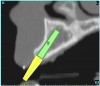
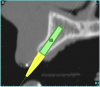
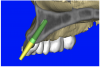
Using the interactive treatment-planning software application, the scan data was assimilated and both potential lateral incisor implant receptor sites were evaluated. It is a combination of the data and the methodology used to interpret the data that is the basis for defining a new paradigm in diagnosis and treatment planning. Proper evaluation of these images and correct use of the interactive treatment-planning software tools is essential in creating a decision tree of treatment options. First, the data from the scan was reformatted into panoramic, axial, and cross-sectional images. The undistorted cross-sectional images revealed the residual alveolar bone in the area of the right lateral incisor. Then, a simulated schematic implant was placed within the bone with an abutment extension to help visualize the connection to the restorative position of the tooth (Figure 4A). The Triangle of Bone® (TOB), a concept developed by the author to analyze bone quality, quantity, and disposition at prospective dental implant sites using CBCT scans, aided in determining available bone volume by defining a “zone” for proper implant placement18,19 (Figure 4B).
The TOB concept creates a decision tree of seven basic parameters for proper treatment planning (Table 1). These seven parameters should not serve as the final assessment based on only a single image. Rather, the information should be evaluated and assimilated to gain an appreciation of all available images, including the axial, cross-sectional, panoramic, and three-dimensional (3D) reconstructions. These parameters include:
1. Bone Quality—CT scan data allows the clinician to determine bone quality through the interpretation of the gray scale values known as Hounsfield units, and inspect the topography and thickness of the labial and palatal cortical plates.
2. Bone Volume—CT scan data allows the clinician to assess bone volume, which is essential for adequate fixation and vascularity for bone maturity and maintenance.
3. Bone Defects—CT scan data allows the clinician to appraise any bone defects within the zone of the TOB, which is crucial for planning implant or grafting procedures.
4. Implant Length and Width—Undistorted CT scan data and interactive software tools allow the clinician to identify the “zone” from which ideal implant length and width can be determined.
5.Tapered or Straight Implants—With both straight and tapered implants available, the TOB, in combination with other views afforded by CT-scan technology, aids the clinician in determining which type of implant will be best suited for the receptor site.
6. One-Piece Implants—Recently, narrow- and standard-diameter one-stage, one-piece implants for various applications have been advocated by certain implant manufacturers. These implants are extremely technique sensitive, especially ones with premachined margins, and can dramatically limit the restorative phase if placed in less than desirable positions.20,21 The TOB helps the clinician to identify potential receptor sites where one-piece implants can be used successfully.
7. Grafting Procedures—The “zone,” as defined by the TOB, helps the clinician determine whether grafting procedures are required and, additionally, if the graft should be particulate or block bone or limited to soft tissue based on the volume of the defect.
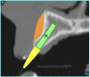
After reviewing the CT data and the decision tree, the bone within the “zone” of the TOB was evaluated and found to be satisfactory for implant placement. Because the goal of implant dentistry is not the implant but the tooth that is placed, true restorative-driven implant dentistry must begin with the assumption that the implant position should remain consistent with the tooth it is replacing, and the final implant-supported restoration.12,22-26 The TOB aids the clinician in understanding the link between the implant position and the desired restorative goal. The base of the geometric shaped “zone” is visualized by starting at the widest area of alveolar bone facially and superiorly. The apex of the triangle is positioned to bisect the alveolar crest (Figure 4B). The TOB, the overlay in the cross-sectional image, reveals whether adequate bone is available for implant placement. It also helps to identify concave facial bone defects, and accurately determine the width of bone at the crest. The author recommends using an interactive software application that provides the necessary measurement tools to accurately assess the bone anatomy.
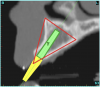
This case contained bilateral concavities, which led to three treatment options being considered: (1) place the bilateral implants and do nothing about the concavity and lack of root eminence; (2) place a soft-tissue graft to plump out the tissue to simulate a root eminence; or (3) add bone to fill out the defect. Additional suboptions also came into play, such as the type of bone graft procedure (allograft or autogenous, particular cancellous or cortical particles, block graft). The left lateral site revealed a thinner facial-lingual crestal dimension (Figure 5A). The simulated implant was placed within the TOB, and a simulated bone graft (available as an upgrade tool for SIM/Plant) was added to the facial, helping determine the proper course of treatment (Figure 5B).
The “Restorative Dilemma”
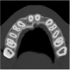
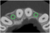
The CT axial views represent an important instrument in gaining a better understanding of anatomical features that can not be determined by any other imaging modality (Figure 6A). When the maxilla is sliced axially at the level where the roots meet the crest of the bone, the adjacent and surrounding root morphology can be revealed. Of note are the individual and different shapes of each of the central incisors, canines, premolars, and molar roots. These images reflect a phenomenon defined by the author as the “restorative dilemma.” Clinicians encounter this often difficult dilemma when attempting to re-establish morphologically correct emergence profiles in prosthetic teeth as they ascend from the round shape of the implant(s). When planning for the placement of the implant in the left lateral incisor area, there appeared to be adequate mesial-distal space between roots as seen in the axial view of Figure 6B. A closer inspection of the planned site for the right lateral incisor revealed a more narrow space, further.complicated by the distal rotation of the palatal aspect of the tooth root. Based on this preliminary position, the 3.75-mm diameter, straight-walled implant can be seen encroaching on the lamina dura periodontal ligament space of the right canine and central incisor. If there was not adequate room for this diameter and type of implant, the adjacent teeth could sustain potential iatrogenic damage. Therefore, additional “tweaking” of the virtual placement was necessary to diminish this risk.
Confirmation With Interactive 3D Imaging
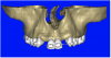
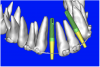
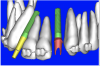
After the basic plan had been established, it was re-evaluated using interactive 3D images. The reconstructed 3D view of the maxilla clearly illustrated the extent of the bilateral facial concavities, and the root eminences of the adjacent and posterior teeth (Figure 7A). The placement of the virtual implants then was evaluated to ensure that the facial cortical plate was not perforated (Figure 7B). The implants were labeled individually as “7” and “10,” with the simulated yellow abutment projection indicating the facial-lingual inclination through the bone to the level above the incisal edge of adjacent teeth. The ability to gain a better understanding of these individual root forms can not be underestimated. The dental literature has suggested certain parameters for placing implants near teeth and implants next to other implants. However, there is little scientific 3D documentation to support these suggested rules.5-10 The use of an interactive treatment-planning software application permits closer scrutiny of previously difficult-to-visualize areas, and can now be used to redefine perceptions of spatial positioning of implants, especially when in close proximity to natural tooth roots, vital anatomy, and adjacent implants.27-29
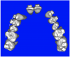
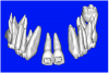
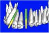
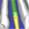
Using different masking (segmentation) and threshold Hounsfield unit values, several new 3D bone volumes can be created which offer invaluable information. To help determine the final position of each implant a new bone model was created with a Hounsfield unit value of 1480, which eliminated all but the densest objects included in the scan data. (Results may vary depending on the CBCT machine used.) The inner and outer layers of bone were removed, leaving the underlying enamel and root structure of the teeth (Figure 8A). After the bone had been stripped away, the root inclinations were examined closely. The most striking findings confirmed the rotated position of the right central, while revealing the slight mesial dilaceration of the root apex, which converged on the space needed for the path of the potential implant (Figure 8B). The schematic shapes of the proposed implants were visualized for the right and left lateral spaces in different rotations of the 3D maxillary arch. It was at this point that a determination was made as to the appropriate implant shape and type that would fit the available space while avoiding encroachment on adjacent tooth roots. A tapered design implant (Tapered Screw-Vent®, Zimmer Dental, www.zimmerdental.com) was chosen from the large virtual library. With the SIMPlant software, the virtual library contains data from dozens of implant manufacturers and realistic computer-aided design representations as seen in Figure 9A through the translucent bone. The position of the left implant can be visualized with adequate mesial-distal distance between adjacent tooth roots (Figure 9B) and a more delicate placement (Figure 9C).
The Restorative Link— “Virtual Teeth”
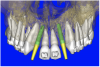
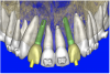
However with all of this preliminary planning, the most important aspect was yet to be addressed—the relationship of the bone, implant, and abutment to the final restoration, the implant crown. Before the advent of interactive treatment-planning software applications, the only reliable method to incorporate tooth information was through a scannographic radiopaque template worn by the patient during the scanning process. This highly desirable planning aid required prior laboratory preparation. While still in its early phase of implementation, the use of a virtual tooth tool provided an additional innovative 3D planning aid, which was used for this case. Virtual teeth allowed for a final inspection of implant and abutment positioning, without a scanning appliance (Figure 10A). The abutment projection was evaluated for a cementable prosthesis (Figure 10B) and, if it had been required, the abutment easily could have been changed to an angulated version. (The software provides the ability to customize the degree of inclination.) The final shape of the virtual teeth can be seen in Figure 10C. The combination of interactive 3D models, multiple volume renderings, realistic implants, realistic abutments, and virtual teeth created a powerful set of tools in the author’s quest to achieve true restorative-driven implant dentistry defining new paradigms for assessing patient anatomy for implant planning.
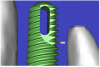
By using interactive treatment-planning software, the author was able to assess implant-to-tooth distances based on actual undistorted measurement of distances at both the crest (Figure 11A) and the apex (Figure 11B) of the implant. Additionally, the ability to section the 3D model allowed extremely accurate virtual implant placement, ensuring 2 mm of facial and palatal bone surrounding the implant (Figure 12A). Using advanced masking tools, further manipulation of the 3D maxilla provided an unparalleled appreciation not only of the potential implant receptor sites, but also of the alveolar complex of each existing tooth and root morphology (Figure 12B).
After the plan was finalized, the data was sent via e-mail for the fabrication of the CT-derived templates (Materialise Dental). Current software applications offer various methods for template fabrication, which can include: (1) bone-borne; (2) tooth-borne; and (3) soft tissue-borne. This case presented with an almost complete dentition, ideal for a tooth-borne template. When evaluating software/hardware solutions, it is important to determine what type of templates can be fabricated from the CT dataset.30-39
Surgical Phase
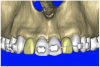
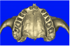
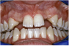
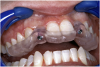
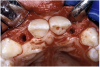
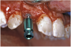
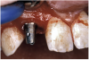
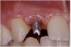
Before the day of surgery, the patient was seen by the orthodontist for the removal of the orthodontic brackets. The patient still was not pleased with the position of the two centrals, and it was determined that this would be addressed after implant placement (Figure 13A). The anatomical variations of the crestal tissue and lack of interdental papilla can be appreciated in the close-up views of the right and left sites (Figure 13B and 13C). There were no surprises on the day of surgery as all of the decisions were made during the planning phase, before the scalpel ever touched the patient. The occlusal view of the CT 3D model revealed the wider alveolar ridge on the right side and thinner crest on the left side (Figure 14A). This was confirmed when the full thickness mucoperiosteal flaps were elevated, and the underyling bone revealed (Figure 14B). The tooth-borne templates were designed to facilitate the drills and drilling sequence specific to the diameters of the predetermined implants (Figure 15A). Each template contained an embedded 5-mm long stainless steel tube, which was approximately 0.2-mm wider than each drill (just wide enough to allow for the drills to rotate freely). Once positioned over the natural teeth, the template was secure and offered precision accuracy in transferring the implant locations from the original software-designed plan, allowing the potential for internal and external irrigation (Figure 15B).
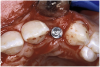
The 3.7-mm diameter Tapered Screw-Vent implant drilling sequence required three drills: pilot, intermediate, and final sizing. Thus, three separate templates were fabricated to accommodate these sizes. The templates were removed easily and replaced with the next sequential size in less time than it takes to change the drill on the surgical handpiece. After the osteotomies had been completed, the implants were delivered to the site (Figure 16A and Figure 16B). For this internal hex connection implant, the author r.commends that the flat of the antirotational hex be positioned to the facial for proper orientation of the restorative components (Figure 17A). Preprepared margins were created from a milled titanium fixture mount transfer post, which was delivered to the implant as support for an immediate transitional restoration. The facial “dot” helped confirm the orientation of the abutment to the facially positioned flat side of the internal hex connection (Figure 17B). Before cementation of the transitional acrylic restorations, a closed-tray, fixture-level impression was made, and a soft-tissue model fabricated.
Restorative Phase
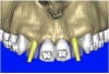
The software used facilitated the author in controlling the precise orientation of the rotation of the implant. As a result, the internal antirotational feature of the implant could be positioned to the desired location. The occlusal view in Figure 18A shows the point of the internal hex connection rotated to the facial. As stated previously, implant manufacturers fabricate component parts, such as stock angulated abutments, to fit as oriented to the flat of the hex. Therefore, software tools have been created to allow precise control over this rotational position so that the hex could be placed in the proper virtual position (Figure 18B). The importance of this software feature has been amplified by the recent addition of realistic stock abutments for the many implant manufacturers who have provided this data for inclusion in the virtual implant library. The ability to choose and evaluate stock components during the virtual interactive planning phase empowers the clinician to achieve a higher level of sophistication to maximize presurgical prosthetic planning. New planning tools are being added to these software systems regularly. An example of a planning tool in development at the time of the present article included the direct fabrication of site-specific, custom computer-milled abutments (as pioneered by the author when presented at the March 2005 Academy of Osseointegration meeting), potentially eliminating the necessity for fixture-level transfer impressions.40 The treatment-planning software plan was exported for fabrication of a patient-specific, computer-milled abutment (Figure 19A). The virtual abutment design process was carried out on the computer, and a virtual abutment was designed and produced directly from the CT dataset, without an impression or physical model (Figure 19B) (Atlantis Components, Inc, www.atlantiscomp.com).
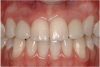
The transitional titanium abutments were left in place for 8 weeks. During this time, the morphologically shaped, computer-milled abutments supported the interproximal tissue and developed the desired emergence profiles. The computer-milled abutments were created to accommodate the adjacent teeth and opposing occlusion, and to aid in the fabrication of the final porcelain-fused-to-metal (PFM) restorations (Figure 20A and Figure 20B). The final crowns were delivered 4 months after implant placement. The radiograph of the emergence profile confirmed the seamless fit of the abutment-implant-crown interfaces (Figure 21). The final restorations were esthetic, functional, and met the needs of the patient (Figure 22A). The re-establishment of the interdental papilla completed the careful transformation of the flat alveolar crestal tissue into a proper emergence of the clinical PFM crowns, indistinguishable from the surrounding dentition (Figure 22B).
Conclusion
Since dental implants have been used to replace missing teeth, 2D imaging modalities have been the primary tool used to assess the available bone and vital structures. With the advent of CT scan technology and, more recently, the introduction and widely accepted use of CBCT technology, clinicians have the opportunity to expand on their ability to effectively diagnose and treatment plan. The evolution of virtual treatment-planning software applications empowers clinicians with enhanced diagnostic capabilities for both the surgical and restorative phases of implant reconstruction.
Interactive treatment-planning software containing sophisticated tools enables closer inspection of previously difficult- or impossible-to-visualize areas. The combination of interactive 3D models, multiple volume renderings, realistic virtual implants, realistic virtual abutments, and virtual teeth creates a powerful set of tools for the quest to achieve true restorative-driven implant dentistry. These new tools likely will be used to define new paradigms that will redefine the dental communities’ perceptions of spatial positioning of implants, especially when in close proximity to natural tooth roots, vital anatomy, and adjacent implants. Assessing implant-to-tooth distances based on actual, undistorted measurement of distances at both the crest and the apex of the implant now can be a.complished easily. Clinicians who may be unfamiliar with CT imaging readily can understand and appreciate a virtual interactive model of a patient’s maxilla or mandible. The ability to manipulate 3D models allows for extremely accurate implant placement, ensuring adequate bone volume surrounding the implant. Additionally, using advanced masking tools provides unparalleled appreciation of potential implant-receptor sites and the alveolar complex of each existing tooth, providing an exceptional methodology for understanding patient anatomy. As demonstrated, these innovative tools have allowed for new paradigms to be developed, which eventually may supersede previous methods of presurgical planning for dental implant reconstruction.
Disclosure
At the time this article was first written, the author was a consultant for and received honoraria from Materialise Dental and Atlantis Components, Inc. He also has received honoraria from Zimmer Dental in the past.
References
1. Brånemark PI, Hansson BO, Adell R, et al. Osseointegrated implants in the treatment of the endentulous jaw. Experience from a 10-year period. Scan J Plast Reconstr Surg. 1977;11(Suppl 16):1-132.
2. Adell R, Lekholm U, Rockler B, et al. A 15-year study of osseointegrated implants in the treatment of the edentulous jaw. Int J Oral Surg. 1981;10(6):387-416.
3. Albrektsson T, Zarb GA, Worthington P, et al. The long-term efficacy of currently used dental implants: a review and proposed criteria for success. Int J Oral Maxillofac Implants. 1986;1(1):11-25.
4. van Steenberghe D, Lekholm U, Bolender C, et al. Applicability of osseointegrated oral implants in the rehabilitation of partial edentulism: a prospective multicenter study on 558 fixtures. Int J Oral Maxillofac Implants. 1990;5(3):272-281.
5. Salama H, Salama M. Garber D, et al. Developing optimal peri-implant papillae within the esthetic zone. Guided soft tissue augmentation. J Esthet Dent. 1995;7(3):125-129.
6. Tarnow DP, Eskow RN. Preservation of implant esthetics: soft tissue and restorative considerations. J Esthet Dent. 1996:8(1):12-19.
7. Tarnow DP, Cho SC, Wallace SS. The effect of inter-implant distance on the height of the inter-implant bone crest. J Periodontol. 2000:71(4):546-549.
8. Small PN, Tarnow DP. Gingival recession around implants: a 1-year longitudinal prospective study. Int J Oral Maxillofac Implants. 2000:15(4):527-532.
9. Choquet V, Hermans M, Adriaenssens P, et al. Clinical and radiographic evaluation of the papilla level adjacent to single-tooth dental implants. A retrospective study in the maxillary anterior region. J Periodontol. 2001;72(10):1364-1371.
10. Kois JC, Kan JY. Predictable peri-implant gingival aesthetics: surgical and prosthodontic rationales. Prac Proced Aesthet Dent. 2001;13(9):691-698.
11. Rosenfeld AL, Mecall RA. Use of interactive computed tomography to predict the esthetic and functional demands of implant-supported prostheses. Compend Contin Educ Dent. 1996;17(12):1125-1132.
12. Rosenfeld AL, Mecall RA. Use of prosthesis-generated computed tomographic information for diagnostic and surgical treatment planning. J Esthet Dent. 1998;10(3):132-148.
13. Ganz SD. CT scan technology: an evolving tool for predictable implant placement and restoration. International Magazine of Oral Implantology. 2001;1:6-13.
14. Sonic M, Abrahams J, Faiella R. A comparison of the accuracy of periapical, panoramic, and computerized tomographic radiographs in locating the mandibular canal. Int J Oral Maxillofac Implants. 1994;9:455-460.
15. Ganz SD. Use of conventional CT and cone beam for improved dental diagnostics and implant planning. AADMRT Newsletter. Spring 2005:19-24.
16. Ganz SD. Conventional CT and cone beam CT for improved dental diagnostics and implant planning. Dent Implantol Update. 2005;16(12):89-95.
17. Hatcher DC, Dial C, Mayorga C. Cone beam CT for pre-surgical assessment of implant sites. J Calif Dent Assoc. 2003;31 (11):825-833.
18. Ganz SD. The triangle of bone—a formula for successful implant placement and restoration. Implant Soc. 1995;5(5):2-6.
19. Ganz SD. The reality of anatomy and the triangle of bone. Inside Dentistry. 2006:2(5):72-77.
20. Ganz SD. Advanced computer aided design applications for enhanced esthetics and functional outcomes. Paper presented at: 9th Annual Meeting of ICOI-IPS; August 2006; Montreal, Canada.
21. Parel SM, Schow SR. Early clinical experience with a new one-piece implant system in single tooth sites. J Oral Maxillofac Surg. 2005;63(9 Suppl 2):2-10.
22. Ganz SD. What is the single most important aspect of implant dentistry? Implant Soc. 1994;5(1):2-4.
23. Garber DA. The esthetic dental implant: letting restoration be the guide. J Oral Implantol. 1996;22(1):45-50.
24. Garber DA, Belser UC. Restoration-driven implant placement with restoration-generated site development. Compend Contin Educ Dent. 1995;16(8):796-804.
25. Amet EM, Ganz SD. Implant treatment planning using a patient acceptance prosthesis, radiographic record base, and surgical template. Part 1: presurgical phase. Implant Dent. 1997;6(3):193-197.
26. Rosenfeld AL, Mandelaris GA, Tardieu PB. Prosthetically directed placement using computer software to insure precise placement and predictable prosthetic outcomes. Part 1: diagnostics, imaging, and collaborative accountability. Int J Periodontics Restorative Dent. 2006;26(3):215-221.
27. Ganz SD. Use of stereolithographic models as diagnostic and restorative aids for predictable immediate loading of implants. Pract Proced Aesthet Dent. 2003;15(10):763-771.
28. Ganz SD. Presurgical planning with CT-derived fabrication of surgical guides. J Oral Maxillofac Surg. 2005;63(9 Suppl 2):59-71.
29. Ganz SD. Techniques for the use of CT imaging for the fabrication of surgical guides. Atlas Oral Maxillofac Surg Clin North Am. 2006;14(1):75-97.
30. Fortin T, Champleboux G, Lormée J, et al. Precise dental implant placement in bone using surgical guides in conjunction with medical imaging techniques. J Oral Implantol. 2000;26(4):300-303.
31. Sammartino G, Della Valle A, Marenzi G, et al. Stereolithography in oral implantology: a comparison of surgical guides. Implant Dent. 13(2):133-139.
32. Sarment DP, Al-Shammari K, Kazor CE. Stereolithographic surgical templates for placement of dental implants in complex cases. Int J Periodontics Restorative Dent. 2003;23(3):287-295.
33. Casap N, Tarazi E, Wexler A, et al. Intraoperative.computerized navigation for flapless implant surgery and immediate loading in the edentulous mandible. Int J Oral Maxillofac Implants. 2005;20(1):92-98.
34. Tardieu PB, Vrielinck L, Escolano E. Computer-assisted implant placement. A case report: treatment of the mandible. Int J Oral Maxillofac Implants. 2003;18(4):599-604.
35. Di Giacomo GA, Cury PR, de Araujo NS, et al. Clinical application of stereolithographic surgical guides for implant placement: preliminary results. J Periodontol. 2005;76(4):503-507.
36. Marchack CB, Moy PK. The use of a custom template for immediate loading with the definitive prosthesis: a clinical report. J Calif Dent Assoc. 2003;31(12):925-929.
37. Klein M. Implant surgery using customized surgical templates: the Compu-Guide Surgical Template System. Interview. Dent Implantol Update. 2002;13(6):41-46.
38. Ganz SD. CT-derived model-based surgery for immediate loading of maxillary anterior implants. Pract Proced Aesthet Dent. 2007;19(5):311-318.
39. Rebaudi A. The Ray Setting procedure: a new method for implant planning and immediate prosthesis delivery. Int J Periodontics Restorative Dent. 2007;27(3):267-275.
40. Ganz SD. Using stereolithographic CT technology for immediate functional and non-functional loading. Paper presented at: Annual Meeting of the Academy of Osseointegration; March 2005; Orlando, Florida.