You must be signed in to read the rest of this article.
Registration on CDEWorld is free. Sign up today!
Forgot your password? Click Here!
Cone-beam computed tomography (CBCT), also referred to as volume imaging CT scan, is a valuable aid in identifying anatomic entities, diagnosing intraoral pathosis, assessing the height and width of alveolar bone, and treatment planning in dental implant cases.1 Historically, intraoral radiographs provided 2-dimensional (2-D) projections of structures, whereas CBCT allows for 3-dimensional (3-D) acquisition of data and image reconstruction.1 This change has aided proper implant placement, thereby reducing untoward surgical and prosthetic sequelae.2
CBCT imaging is sometimes referred to as a CAT (computerized axial tomography) scan. Both capture the same information with respect to dental osseous structures; however, the two scanning methods are distinguishable. For instance, with CBCT, a single x-ray source produces a cone beam of radiation that captures a large volumetric area. The x-ray source and detector rotate around the patient one time. Multiple projections are acquired and reconstructed using algorithms to produce 3-D images. In contrast, a CAT scan uses a fan beam, and the machine makes multiple revolutions around the patient’s head to collect adequate information, which results in overlapping radiation.2 For intraoral visualization, CBCT scans are usually ordered instead of a CAT scan because they induce less radiation, have lower equipment costs, and facilitate simpler image acquisition.1,2
Authors have suggested that an informed consent document alone signed by patients that advises them of potential risks associated with implant dentistry may not provide an adequate legal defense in problematic cases. For example, Curley and Hatcher3 caution that when a dental drill penetrates the inferior alveolar canal and causes paresthesia, there may be legal consequences if a patient was not offered the opportunity to have presurgical diagnostic CBCT imaging, because it may have provided information to avoid such a complication. Ultimately, the decision to order a CBCT scan is a judgment call by the treating clinician, and this choice will depend on many factors. One factor is the need for additional information that may be furnished by CBCT imaging.2 Therefore, it is incumbent upon clinicians to become familiar with information supplied by a CBCT scan, which provides a variety of different views—including cross-sectional, panoramic, and axial—and the ability to rotate the entire volume and inspect it from different perspectives.
The American Academy of Oral and Maxillofacial Radiology has recommended that some form of cross-sectional tomographic images be used to enhance treatment planning of dental implant cases.2 These views facilitate measurements of the buccolingual dimensions and heights of maxillary and mandibular ridges, they help identify osseous undercuts, and they depict sites where structures (eg, the inferior alveolar nerve) preclude implant placement.
This article is a primer on how to read and interpret CBCT cross-sectional views. Several panoramic views are included because they provide a broader view of some anatomic regions and are used in conjunction with cross-sectional views. Maxillary and mandibular structures of interest will be illustrated and described with respect to their clinical relevance to facilitate application of this knowledge to treatment planning.
Clinical and Radiographic Examination
When examining a CBCT scan, the clinician has the responsibility to examine every cross-section to ensure that no pathosis is overlooked. It is suggested, though not mandatory, to begin viewing the last section on the left side (this corresponds to the patient’s right side) and proceed anteriorly examining one slice (also referred to as a cut or cross-section) at a time.4 Cross-sectional cuts are usually 1-mm thick but can vary depending on the software.4 At the periphery of each cross-sectional cut there are millimeter markings horizontally and vertically that facilitate measuring the dimensions of structures. The computer also can be used to perform measurements of structures and edentate spaces. The use of radiopaque markers (eg, barium sulfate) at the time of scanning facilitates measurements at specific sites. In conjunction with a radiographic assessment, a thorough clinical examination should be conducted. In addition, when possible, anatomic structures should be palpated and restorative space (eg, vertical height and horizontal width) of edentulous areas measured.
Mandibular Structures Mandibular Foramen and Lingula
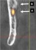
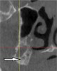
One of the first landmarks noticed in the posterior mandible is the mandibular foramen. At this site, the inferior alveolar nerve enters the ramus (Figure 1). When administering a mandibular block injection, it is often advisable to insert the needle 6 mm to 10 mm above the occlusal plane,5 because the mandibular canal is coronal to the occlusal plane 2% to 25% of the time.6,7 Therefore, an injection at the occlusal plane may result in failure to attain a good anesthetic result. The ridge superior to the foramen is the lingula, and the sphenomandibular ligament inserts at this location (Figure 1).
Inferior Alveolar Canal
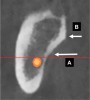
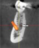
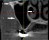
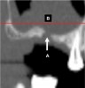
Proceeding anteriorly, the inferior alveolar nerve (IAN) (Figure 2) may descend gently or steeply in the mandible.8 The canal is usually around 3.2-mm wide and surrounded by cortical bone, which does not reliably provide resistance to a twist drill.9 In order to determine the length of a dental implant at a specific site in the posterior mandible, it is advisable to measure from the crest of the alveolar bone to the coronal aspect of the IAN and subtract 2 mm to provide a safety zone.10
Submandibular Fossa and Mylohyoid Ridge
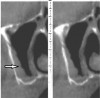
The submandibular fossa is denoted by an undercut in the posterior mandible (Figure 3). It is located beneath the mylohyoid muscle. This site must be intraorally palpated before implant placement because there may be an undercut in the mandibular molar area. In this regard, Parnia et al reported that 52% of patients manifest concavities 2 mm to 3 mm deep, and 28% of the examined regions demonstrated concavities of more than 3 mm.11 Thus, when there is a large undercut, caution must be exercised in order to avoid drilling into the floor of the mouth, which could sever a blood vessel and result in hemorrhaging. The ridge on the lingual aspect of the mandible depicted in Figure 3 is the mylohyoid ridge, which provides the origin of the mylohyoid muscle.
Mental Foramen
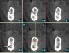
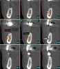
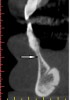
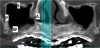
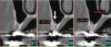
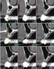
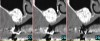
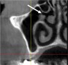
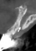
In the first molar and/or second premolar area, the IAN usually splits into two nerves: the mental and incisive nerves.10 The mental foramen is where the mental nerve emerges from the mental canal. During examination of the cross-sections, it is evident that the mental canal creates a distinct radiolucency that extends through the buccal cortical plate of bone (Figure 4). This is an important landmark because the nerve that continues anterior to the mental foramen is the incisive nerve and drilling into it will not cause paresthesia, whereas penetrating into the IAN or mental nerve may result in paresthesia.10 It is important to inspect cross-cut sections anterior to the mental foramen to ensure that there is no anterior loop of the mental foramen. A loop occurs when the IAN goes inferiorly and anteriorly to the mental foramen and loops back to enter the canal.10 It can appear as two distinct oval canals or it may have a “C” shape (Figure 5). Contrastingly, in the absence of an anterior loop mesial to the mental foramen, there will be no secondary radiolucencies in the bone (Figure 6). In the absence of a loop, a long implant can be placed because penetration into the incisive nerve will not cause paresthesia.10
Marrow Space
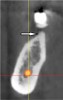
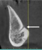
A marrow space, which is depicted in Figure 7, can occur within the cancellous bone and can be 200-μm to 2,000-μm wide.12 Radiographically, the space appears to be hollow and provides no resistance to the twist drill when entered. In the mandible, during the creation of an osteotomy above the nerve, a finger rest or a drill stop should be employed to avoid unexpectedly falling into a marrow space.
Ridge Contour
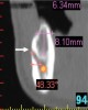
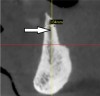
The contour of a ridge is a critical determinant with regard to the width of an implant being considered for insertion. The crest of the ridge presented in Figure 8, for example, offers several treatment options. During development of an osteotomy, an implant can be placed and, if drilling causes a bone dehiscence on the buccal or lingual aspect of the ridge, a bone graft can be applied under a cell-occlusive barrier. Alternatively, if there is enough bone height, the ridge can be vertically reduced until a thicker part of it is available to create an osteotomy. Other treatment options for a thin ridge include ridge splitting and guided bone regeneration to enhance ridge contour. It should be noted that, intraorally, a ridge might appear to be thin; however, a CBCT scan may confirm that there is an adequate amount of bone (ie, wider ridge) available for implant placement (Figure 8).
Hourglass Configuration of the Mandible
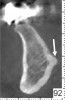
The “hourglass” shape, which is an unusual shape of the mandible, results from an osseous constriction at the alveolar–basal bone junction. This type of mandible is atypical and occurs around 3.9% of the time (Figure 9).13 This developmental or genetic variant poses a significant anatomic challenge for dental implant surgery. In such an instance, bone grafting is necessary to restore the ridge before implant placement, or a substantial amount of ridge reduction can be performed (these are very advanced therapies). Alternatively, these difficult sites can be skipped and another location selected for implantation.
Lingual Foramen
In this region, the sublingual blood vessel from the floor of the mouth (sublingual artery) anastomoses with the buccal vasculature (Figure 10). If during osteotomy creation the drill penetrates into this canal, there may be more bleeding than usual. Placement of a guide pin or the implant into the osteotomy will arrest the hemorrhaging.14
Cortical vs Cancellous Bone
It is important to verify that there is cancellous bone between the buccal and lingual cortical bony plates when considering a ridge expansion or ridge split procedure, because fused cortical plates will not expand or split (Figure 11).
Superior and Inferior Genial Tubercles
The genial tubercles are small bony elevations found on the lingual aspect of the mandible (Figure 12). They are situated on either side of the midline and provide the area of origin for the genioglossus muscle (attaches to the superior tubercle) and geniohyoid muscle (attaches to the inferior tubercle).15 When flaps are reflected for surgical access, the genioglossus muscle should not be completely elevated off the tubercle, because the tongue may retract to the posterior part of the throat and block the airway.16 In a severely resorbed mandible, the superior genial tubercle may be at the ridge crest and appear as a lingual bony protuberance.
Maxillary Structures Maxillary Tuberosity
The maxillary tuberosity (Figure 13) is a rounded structure on the distal surface of the body of the maxilla, behind the root of the third molar. This site is sometimes used to harvest bone graft material.
Maxillary Sinus
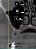
The maxillary sinus is the largest of the paranasal sinuses (Figure 14).17 The average height of this pyramid-shaped sinus is 36 mm to 45 mm.17 It is lined by the Schneiderian membrane, which can become thickened due to smoking or other pathosis (Figure 15). Lateral window sinus lifts are performed by creating a window through the buccal plate of bone adjacent to the sinus, elevating the Schneiderian membrane, and inserting bone into the inferior third of the sinus. The maxillary sinus is surrounded by six walls18:
- Anterior wall (Figure 16): This contains the infraorbital nerve and blood vessels to the anterior teeth.
- Superior wall (Figure 16): It is thin and makes up the orbital floor.
- Posterior wall (Figure 16): This corresponds to the pterygomaxillary region, which separates the antrum from the pterygopalatine fossa.
- Medial wall: It separates the sinus from the nasal fossa.
Sinus floor (Figure 16): It may extend in between the roots of the maxillary molars. If a sinus lift is performed and a fenestration in the bony floor of the sinus is detected on the CBCT scan (Figure 17), then a flap needs to be elevated on the ridge and the tissue protruding into the ridge needs to be pushed into the sinus.19 Otherwise, when the Schneiderian membrane is elevated internally, the membrane will tear in this region. Sometimes a pseudocyst can appear on the floor of the sinus (Figure 18).
Lateral wall: This wall provides access for the sinus graft procedure. A small radiolucency in the buccal plate indicates the presence of a blood vessel (Figure 19). After a failed sinus lift, a CBCT scan may demonstrate a large fenestration in the buccal plate of bone (Figure 20). To accomplish a sinus lift in this region, a split-thickness flap needs to be elevated, and the connective tissue left over the window needs to be pushed into the sinus because it is attached to the re-formed Schneiderian membrane.19 Figure 21 depicts a completed sinus lift procedure where the bone that was inserted did not reach the medial wall of the sinus.
Ostium
The ostium is the opening from the sinus to the middle meatus of the nose (Figure 22). It is situated on the superior aspect of the medial wall of the maxillary sinus above the first molar. The distance from the most inferior point of the antral floor to the ostium is, on average, 28.5 mm.17 The size of the ostium is usually 2 mm to 3 mm wide.20 Therefore, if bone graft particles after a sinus lift become loose in the sinus, the cilia sweep them through the ostium into the nose.
Septa
Septa are projections of bone into the sinus, and they may partially or completely compartmentalize the maxillary sinus (Figure 19). They have been located in 31% of maxillary sinuses in the premolar area and usually do not compartmentalize the antrum.21 Septa are usually found adjacent to the medial wall of the sinus. When they are present within the operative field of a lateral window or transcrestal sinus lift procedure, they increase the risk for membrane perforation when the membrane is elevated. (Note: Septum is the singular form of septa [plural].)
Zygomatic Arch
The zygomatic arch, or cheekbone, consists of the zygomatic process of temporal bone and the temporal process of the zygomatic bone (Figure 14). Sometimes, due to a patient’s anatomy the zygomatic arch will be superimposed upon the sinus in a 2-D radiograph and obscure important diagnostic information.
Nasopalatine Canal
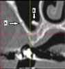
Located between and lingual to the maxillary central incisors (if they are present), the nasopalatine foramen is also referred to as the incisive foramen (Figure 23). Upon flap reflection within the foramen, two lateral canals are noticeable; these are called incisive canals.22 They transmit the anterior branches of the descending palatine vessels and the nasopalatine nerves. Sometimes it is necessary to place an implant into this canal when the premaxilla is extremely resorbed. The nasopalatine foramen is approximately 4.6 mm wide and 8 mm to 12 mm long and is around 7.4 mm from the labial surface of an unresorbed ridge.22
Concha, or Turbinates
In the nose, there is an inferior, middle, and superior turbinate (Figure 24). These structures are also called concha. The inferior turbinate is an independent facial bone, whereas the middle and superior turbinates are part of the ethmoid bone. When the mucosa around a turbinate is inflamed, the turbinate appears distended.
Conclusion
CBCT scans provide valuable diagnostic information for treatment planning in implant cases and are more accurate than periapical or panoramic films.23 Sonick et al reported mean radiographic linear distortions associated with periapical films (14%), panoramic images (23%), and computerized tomography scans (1.8%).23 CBCT imaging furnishes excellent diagnostic yields at a reasonable radiation dose risk.2 Different views (eg, cross-sectional, axial, panoramic) facilitate inspection of osseous structures. This article has focused on cross-sectional views and correlated these images to anatomic information to facilitate treatment planning. Ultimately, correct interpretation of CBCT reformatted images facilitates accurate implant placement and helps avoid unnecessary complications.
Disclosure
The authors had no disclosures to report.
About the Authors
Gary Greenstein, DDS, MS
Clinical Professor
College of Dental Medicine
Columbia University
Private Practice
Surgical Implantology and Periodontics
Freehold, New Jersey
Joseph R. Carpentieri, DDS
Clinical Assistant Professor
College of Dental Medicine
Columbia University
Private Practice
Surgical Implantology and Prosthodontics
White Plains, New York
John Cavallaro, DDS
Clinical Professor
College of Dental Medicine
Columbia University
Private Practice
Surgical Implantology and Prosthodontics
Brooklyn, New York
Queries to the author regarding this course may be submitted to authorqueries@aegiscomm.com.
References
1. Scarfe WC, Farman AG. What is cone-beam CT and how does it work? Dent Clin North Am. 2008;52(4):707-730.
2. Tyndall DA, Price JB, Tetradis S, et al; American Academy of Oral and Maxillofacial Radiology. Position statement of the American Academy of Oral and Maxillofacial Radiology on selection criteria for the use of radiology in dental implantology with emphasis on cone beam computed tomography. Oral Surg Oral Med Oral Pathol Oral Radiol. 2012;113(6):817-826.
3. Curley A, Hatcher DC. Cone beam CT—anatomic assessment and legal issues: the new standards of care. J Calif Dent Assoc. 2009;37(9):653-662.
4. Angelopoulos C. Cone beam tomographic imaging anatomy of the maxillofacial region. Dent Clin North Am. 2008;52(4):731-752.
5. Malamed SF. Handbook of Local Anesthesia. St Louis, MO: Mosby; 1986.
6. Mwaniki DL, Hassanali J. The position of mandibular and mental foramina in Kenyan African mandibles. East Afr Med J. 1992;69(4):210-213.
7. Mbajiorgu EF. A study of the position of the mandibular foramen in adult black Zimbabwean mandibles. Cent Afr J Med. 2000;46(7):184-190.
8. Anderson LC, Kosinski TF, Mentag PJ. A review of the intraosseous course of the nerves of the mandible. J Oral Implantol. 1991;17(4):394-403.
9. Ikeda K, Ho KC, Nowicki BH, Haughton VM. Multiplanar MR and anatomic study of the mandibular canal. AJNR Am J Neuroradiol. 1996;17(3):579-584.
10. Greenstein G, Tarnow D. The mental foramen and nerve: clinical and anatomical factors related to dental implant placement: a literature review. J Periodontol. 2006;77(12):1933-1943.
11. Parnia F, Fard EM, Mahboub F, et al. Tomographic volume evaluation of submandibular fossa in patients requiring dental implants. Oral Surg Oral Med Oral Pathol Oral Radiol Endod. 2010;109(1):e32-e36.
12. Kraus VB, Feng S, Wang S, et al. Trabecular morphometry by fractal signature analysis is a novel marker of osteoarthritis progression. Arthritis Rheum. 2009;60(12):3711-3722.
13. Butura CC, Galindo DF, Cottam J, et al. Hourglass mandibular anatomic variant incidence and treatment considerations for all-on-four implant therapy: report of 10 cases. J Oral Maxillofac Surg. 2011;69(8):2135-2143.
14. Greenstein G, Cavallaro JS Jr, Tarnow DP. Clinical pearls for surgical implant dentistry: part 2. Dent Today. 2010;29(8):64-68.
15. Baldissera EZ, Silveira HD. Radiographic evaluation of the relationship between the projection of genial tubercles and the lingual foramen. Dentomaxillofac Radiol. 2002;31(6):368-372.
16. Misch CE. The division C mandible: mandibular complete and unilateral subperiosteal implants. In: Misch CE, ed. Contemporary Implant Dentistry. 2nd ed. St Louis, MO: Mosby; 1999:434-435.
17. Uchida Y, Goto M, Katsuki T, Akiyoshi T. A cadaveric study of maxillary sinus size as an aid in bone grafting of the maxillary sinus floor. J Oral Maxillofac Surg. 1998;56(10):1158-1163.
18. Misch CE. The maxillary sinus lift and sinus graft surgery. In: Misch CE, ed. Contemporary Implant Dentistry. 2nd ed. St Louis, MO: Mosby; 1999:469-470.
19. Cavallaro JS Jr, Greenstein G, Tarnow DP. Clinical pearls for surgical implant dentistry: Part 3. Dent Today. 2010;29(10):134-139.
20. Aust R, Drettner B. The functional size of the human maxillary ostium in vivo. Acta Otolaryngol. 1974;78(5-6):432-435.
21. Ulm CW, Solar P, Krennmair G, et al. Incidence and suggested surgical management of septa in sinus-lift procedures. Int J Oral Maxillofac Implants. 1995;10(4):462-465.
22. Mraiwa N, Jacobs R, Van Cleynenbreugel J, et al. The nasopalatine canal revisited using 2D and 3D CT imaging. Dentomaxillofac Radiol. 2004;33(6):396-402.
23. Sonick M, Abrahams J, Faiella RA. A comparison of the accuracy of periapical, panoramic, and computerized tomographic radiographs in locating the mandibular canal. Int J Oral Maxillofac Implants. 1997;9(4):455-460.