You must be signed in to read the rest of this article.
Registration on CDEWorld is free. Sign up today!
Forgot your password? Click Here!
Digital workflow in restorative dentistry can streamline processes, but it can be confusing due to misunderstood terminology and the steps needed to be successful with digital dental services. The objectives to be discussed within this article are as follows:
• The flow: radiographs, photographs, and impression taking (digital or analog impressions), along with next-visit sequencing
• Taking digital impressions and delivering the information by email for digital design of crowns for natural dentition
• Workflow for a single maxillary central incisor implant-supported crown in the smile zone
• Handling a maxillary central incisor resulting from trauma with guided smile technology
• Multiple implants in the smile zone and immediately loading the provisionals
• Laboratory choices and communications in the digital workflow in restorative dentistry, along with the expectations for a positive outcome
The Flow: Initial Diagnostic Appointment
The initial diagnostic appointment with a dental patient is crucial. The technology available with digital radiology, digital impression taking, and digital photography allows the clinician to bring to life the real problem or concern the patient is expressing—realized or not by the patient. This is the discovery moment for the patient and the opportunity for the clinician to deliver the information and diagnosis with a solution or chief benefit expected from treatment. A dental practice that has an established digital workflow in progress can acquire radiographs, impressions, and photographs in a 30-minute appointment.1 These duties can be completed by ancillary staff while the doctor is attending to another patient.
Photography
Patient education is critical to treatment success. It is only after allowing patients to see the evidence-based indications for treatment that they can truly take ownership of the process of improving their oral health. Being shown similar cases the dentist has treated, in the form of before and after images, empowers the patient to make better-informed treatment decisions. A camera snapshot can document the conditions of the mouth from tissue architecture to tooth position, condition, and contour. The image can aid in risk assessment in evaluating the progression of disease. Archived images, just like dental x-rays, allow the clinician to compare the patient's current state to the time when images were recorded. The American Academy of Cosmetic Dentistry has a standard photographic protocol composed of 12 views used as an assessment tool in evaluating the indications for and results of treatment; the protocol provides an excellent outline to begin documentation.2,3
Intraoral Scanner
Scanners that are available to the clinician are powder free and have an open file system based on ultrafast optical scanning technology. Color scanning allows the clinician to more easily identify the preparation margins. Some systems can automatically read the shades of adjacent teeth while scanning and provide the information with the digital impression. These systems now have automated shade matching and take digital intraoral photographs, allowing the acquisition of high-definition photos for documentation or communication purposes. Unwanted objects (tongue, cheeks, or lips) can be detected automatically and digitally removed from the digital impression in real time.4
The making of conventional dental impressions of tooth preparations using polyvinyl or polyether materials is a common procedure completed routinely in most dental practices today. However, studies have shown that many of these conventional dental impressions that are sent to dental laboratories are unsatisfactory due to flaws such as voids and bubbles at critical regions of the impression.5,6 Moreover, distortion and expansion of gypsum, used in the making of stone dental casts, can further reduce the accuracy of the conventional dental restoration fabrication process.7
Because computer-aided design/computer-aided manufacturing (CAD/CAM) requires digital models, the interest in intraoral digital impression making has increased to circumvent the conventional production of stone casts using conventional impression materials.8 Today, intraoral digital impression making of tooth preparations for the CAD/CAM-based fabrication of dental prostheses can be accomplished with systems in the marketplace. Digital intraoral acquisition systems allow the dentist to capture the surface of the prepared teeth intraorally in three dimensions (3D), enabling an almost completely digital workflow. CAD/CAM dentistry has transformed and revolutionized the way dentistry is practiced. Five of six scanners studied by the American Dental Association have an open architecture, which means that the acquired digital files can be transferred with an open connection that allows the laboratory to use virtually any CAD/CAM system for the fabrication of restorations.4This increases the flexibility and versatility of the process. CAD/CAM units with closed software programs use files that can only be transferred and used for specific devices.
Radiology
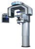
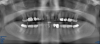
Every dentist has had to make a diagnosis based on the evidence presented during a patient's visit. Traditionally, a periapical radiograph was the line of choice. Changing from film x-rays to digital imaging with 3D cone beam computed tomography (CBCT) has enhanced the dentist's ability to more rapidly and efficiently diagnose (Figure 1). Now, the merging of digital photographs, intraoral scanning, and 3D CBCT data can be delivered to the dental laboratory electronically and ready for prosthetic and surgical treatment planning based on the patient-specific 3D data set taken in one visit at the dental practice. This complete 3D digital patient-specific record creates a hard and biomechanical foundation for accurate 3D planning.8
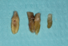
Case 1. Digital Impression and Fabrication of Crowns: Natural Teeth
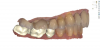
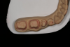
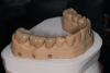
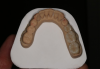
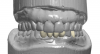
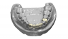
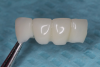
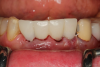
After completing an initial diagnostic appointment, a patient accepted three single-unit full-contour zirconia crowns that were milled from the digital impression and cut back for porcelain application. The application by a technician is analog dentistry. The ability of a dental laboratory to scan an analog crown-and-bridge impression is called converting an analog impression to a digital impression. The workflow after the conversion has become digitized. A dental model is virtually created with computer software, and a full crown proposal is fabricated for inspection virtually before the crown is milled (Figure 2). Due to the color of the digitized impression, the margins of the crown preparations are more easily and rapidly identified. The laboratory will also 3D print a working model, which will be used to develop the morphology of the final restoration by hand placement of porcelain (Figure 3). The decision to prescribe a full contour zirconia crown with cutback for porcelain application or complete full contour zirconia crowns lies solely on the attending dentist.9 A discussion with the patient before preparation of the teeth is imperative. After the discussion, the patient requested the zirconia copings with cutback and porcelain application for the posterior crowns (Figure 4 and Figure 5).
Case 2. Smile Zone Implant: Single Maxillary Central Incisor
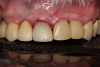
Providing single-tooth restorations in the smile zone can be challenging; considerations for implant dentistry for a single maxillary incisor can be even more challenging. For this case, the digital workflow considerations were not much different from the previous case; radiographs, photography, and analog impressions were used. The patient was given alternative treatment options. He chose a single implant and final zirconia with cutback for porcelain application. The patient was advised about his surrounding vintage dentistry and told he should consider all maxillary anterior teeth, Nos. 6 through 11, be planned for better function and esthetics. The patient had the final say, which allowed the laboratory and the author to finalize the treatment plan with the definitive restoration.
Properly planning this case with digital dental technology offered a large quantity and quality of diagnostic information. Using the dental laboratory software to merge the entire 3D data set helped to predict the best outcome after the digital proposals for the implant abutment and final crown. The patient had been involved with implant dentistry and understood the value of technology available.
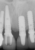
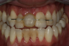
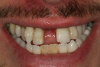
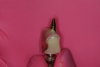
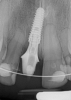
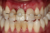
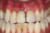
Figure 6 and Figure 7 depict a mature smile with many implant restorations. An analog impression was sent to the laboratory. The impression was scanned by the laboratory, a model was created virtually, and the implant dimensions and position were defined. The 3D surgical guide was fabricated (Figure 8), allowing the patient to receive his therapy swiftly and predictably. Tooth No. 8 was extracted, and the implant was placed and immediately loaded with an acrylic provisional treatment crown (Figure 9). The screw-retained treatment crown was fabricated in-office from a previously completed diagnostic wax-up.
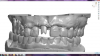
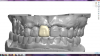
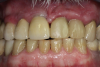
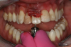
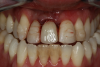
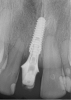
After 4 months of healing and integration of the bone around the implant, the digital workflow was initiated to develop the abutment and treatment plan. Another analog impression was made with an impression post and polyvinyl impression. The laboratory scanned the impression and digitized it to create the emergence profile of the milled titanium abutment and the final restoration (Figure 10 and Figure 11). The patient had a considerably thick soft-tissue profile, allowing a milled titanium abutment. The decision to use a titanium abutment was based on the patient's occlusion and propensity to fracture teeth or restorations. The virtual model was gray because the scanner does not recognize the color of the analog impression. The virtual final abutment and crown were approved and fabrication completed. The final restoration met the patient's esthetic values and his ability to function (Figure 12 and Figure 13).
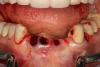
Case 3. TRAUMA: SINGLE Central INCISOR-GUIDED Smile
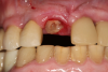
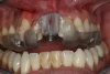
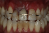
A 23-year-old man reported to the dental practice on January 3. Apparently, while on vacation and celebrating the New Year, the patient experienced a loss of equilibrium and found himself horizontal in the crosswalk. When surveying the damages, his friends noticed he was missing tooth No. 8. Those who were involved were not able to find the missing maxillary central incisor. The young man was eventually seen about 3 days after the trauma. A CBCT radiograph, study models, and photographs were collected, and teeth Nos. 6 through 10 were immobilized with composite and 20 x 20 orthodontic wire (Figure 14). The CBCT and photos were emailed to the dental laboratory, and the analog intraoral impression with a centric occlusion bite registration was sent via ground transportation. Due to the nature of the trauma, the laboratory and the author expeditiously converted the analog diagnostics and merged all the patient's data sets to develop the plan. Based on the 3D data sets, the laboratory and the dentist were able to accurately assess the volume of bone and soft tissue remaining after the trauma. The volume was still intact and soft tissue was plentiful (Figure 15 and Figure 16).
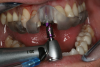
The decision was to develop a surgical guide, place the implant, and fabricate a screw-retained one-piece non-engaging abutment with a slender emergence profile and a polymethyl methacrylate (PMMA) provisional. Ten days after the trauma, the patient was seen in the dental office for the placement of the dental implant. On the day of surgery, a 3D-printed surgical guide was used, developed from the CBCT radiograph and the digitized impressions (Figure 17 and Figure 18).
The rationale for developing this plan through 3D data sets is to accurately, predictably, and expeditiously provide dental services in a highly esthetic area for a young individual. The entire plan can be completed virtually and can provide a greater confidence level for final results and long-term success.8
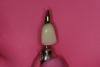
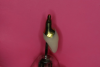
The provisional abutment and treatment crown were fabricated in the laboratory with the digital proposals. Platelet-rich fibrin (PRF) clot technology was incorporated to help with soft- and hard-tissue healing (Figure 19 through Figure 21). The screw-retained provisional and the PRF clot were seated immediately after implant placement (Figure 22 and Figure 23). One 4-0 polytetrafluoroethylene suture was placed to maintain papilla. The teeth immobilization splint was placed for 6 weeks (Figure 24). The rationale for splinting teeth Nos. 6 through 10 was due to noticeable plus-2 mobility of the remaining anterior teeth. The provisional implant crown also was included in the splint.
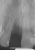
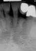
The young man was evaluated at 2 weeks (Figure 25 and Figure 26) and again at 6 weeks (Figure 27). The remaining natural teeth and the implant were stable. The natural teeth had a reduction in mobility to plus 1 at most. The patient's expectation was met. The soft-tissue element of his smile was maintained, and the patient is considering more cosmetic dentistry to optimize his smile. At 16 weeks postoperatively, the radiograph suggested that the digital workflow provided a great benefit to the patient and reduced the amount of chair time in the dental practice, with help from digital technology and the dental laboratory (Figure 28).
Case 4. Immediate Loading: Multiple Implants in the Smile Zone
The term “case workup and virtual prosthetic planning with fully guided or single-unit dental services” will become commonplace. According to Alan Banks, marketing director at Roe Dental Laboratory (Independence, Ohio), when the laboratory first began to move forward with digital dental service, they received only a small number of cases. A year later, the laboratory estimated approximately 20% of their daily cases were requests for digital dental restorations.8
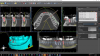
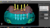
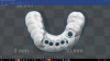
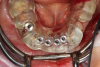
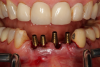
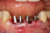
The next case follows the digital protocol for fully guided surgery and prosthetics. A CBCT radiograph, digital impression, and digital photography were the cornerstones to the success of this case. The 3D data set was electronically delivered to the dental laboratory. The data were merged and the process to develop the plan was initiated. The use of CBCT was essential in this case, particularly due to minimal space for placement of individual implants and single-unit crowns. The patient's chief concern was that she wanted to have single-unit crowns instead of fixed crown-and-bridge restorations because she was worried that she would someday find herself in an assisted-living facility; if that were to happen, she wondered, who would help floss under her bridge work? Her decision was to have single implants with individual crowns. CBCT technology is much more accurate in evaluating space maintenance and management.10 Periapicals in the past were rather close for calculating spacing; however, the CBCT identifies the buccal-lingual dimensions as well as the mesial-distal measurements. On review of the completed proposals for implant placement and provisionals, it was determined that there was sufficient spacing for implant placement to allow appropriate emergence profiles for the provisionals and then eventually the final single-unit cemented crowns. The proposal was accepted, and a 3D-printed surgical stent was fabricated, along with the PMMA provisionals (Figure 29 through Figure 35).
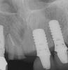
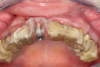
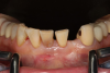
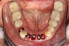
On the day of surgery, the plan was to extract teeth Nos. 21, 23, 24, 25, and 26, place 3.0 x 13-mm implants in the anterior region due to limited spacing, and place a 4.1 x 10-mm implant in the No. 21 extraction site. Before the extractions were performed, the No. 23 pontic was sectioned from the existing 2-unit cantilevered bridge utilizing ceramic and metal high speed rotary cutting burs ZR 6881 and H34L (Komet-USA), respectively. After removal of the pontic and extractions, the surgical guide was verified to be seating positively (Figure 36 through Figure 38). Surgical guide protocol was followed, and all implants were successfully placed and torqued to a value of greater than 35 Ncm (Figure 39 and Figure 40). All implants were placed without flapping, with the exception of No. 23. The flap was elevated to reposition lingual keratinized tissue facially for enhanced esthetic tissue profile. The implants were then prepared with a high-speed carbide bur (Komet-USA) with copious amounts of water (Figure 41 and Figure 42). The one-piece 3.0-mm diameter implant served the needs of the patient's spacing requirements. Inter-occlusal space requirements and path of draw were verified. The PMMA provisionals were air abraded and relined with crown-and-bridge material (Figure 43 through Figure 45).
Due to the guided surgical and prosthetic protocol, this case was completed with tissue sparing and atraumatic extractions with precision implant placement. The most arduous task of the entire procedure was the physical implant abutment preparation for proper clearance. If the patient had more space to plan her treatment, implants using a two-piece protocol would have been implemented with screw-retained non-engaging provisionals after implant placement. Again, this decision process is solely in the hands of the clinician providing services.
Digital workflow for this case was straightforward. The patient was pleasantly surprised with the results. She mentioned that she can now rest easily at night, even if she finds herself in an assisted-care facility.
Laboratory Choice and Communications in Digital Restorative Dentistry
Many dentists have the same questions and concerns about the decision to choose a dental laboratory that satisfies the dentist's digital restorative needs. In the beginning of the new laboratory relationship, the dentist may feel like he or she is swimming in the deep end of a large and unfamiliar swimming pool. Terminology is slightly different, and new principles and perspectives are being created in the digital world. The gratifying news is that the laboratory that is best suited for the dentist who is interested in pursuing digital dentistry is the laboratory that has the dentist's best interests in mind.10All dentists have different interests, skill levels, and knowledge about digital workflow in restorative dentistry. The best laboratories are those that recognize the level of the clinician they are working with and when to encourage the dentist to expand the services with more sophisticated techniques.8
When moving forward with digital workflow, one must remember that the fundamentals and principles regarding digital dentistry are the same as those in traditional analog dental therapies. A dental laboratory will not be able to scan a digital or analog impression if the margins are subgingival. The rule of thumb is, if the margin cannot be seen, the impression cannot be scanned.
In communicating with a digital workflow dental laboratory, it is imperative to meet with the laboratory technician or manager to discuss and develop the relationship and expectations that one has as a clinician when it is time to deliver the final restoration. These discussions should be detailed for all restorative facets, from single crowns to fully guided multi-unit full-mouth rehabilitations.
Conclusion
Digital workflow in restorative dentistry is evolving and accelerating exponentially. The workflow is streamlined and predictable. The laboratory that is proficient and experienced makes the patient experience very desirable. The outcome and expectations are the focal points in digital restorative dentistry. The clinician who is more comfortable with analog techniques can rest assured that the analog techniques can be digitized. For those who may feel more comfortable with digital impression capturing and forging forward with innovation, there is no limit to what may be accomplished in the future. Someday soon patients will request that impressions be taken with a camera, x-rays be taken with a scanner, and photos be emailed, with all information merged into a 3D set to develop a plan, from a single-unit to full-mouth rehabilitation.
Definitions
Workflow: the sequence of industrial, administrative, or other processes through which a piece of work passes from initiation to completion.
Analog: a term used in representing information that uses a continuous range of values. Examples: a CD is digital, a tape is analog; a computer is digital, an abacus is analog. A polyvinyl intraoral impression is considered analog dentistry.
Digital: of, relating to, or being data in the form of especially binary digits, eg, digital images, a digital readout.11 An intraoral scanner for dentistry captures an image and sends an electronic digital impression.
References
1. Ye HQ, Liu YS, Ning J, et al. Constructing 3-dimensional colorized digital dental model assisted by digital photography. Beijing Da Xue Xue Bao. 2016;48(1):138-142.
2. American Academy of Cosmetic Dentistry. A guide to accreditation photography. www.aacd.com/proxy/files/Students%20and%20Faculty/AACD_2013_Photo_Guide(1).pdf. Accessed August 10, 2017.
3. McLaren EA, Terry DA. Photography in dentistry. J Calif Dental Assoc. 2001;29(10):735-742.
4. Hack GD, Patzelt SBM. Evaluation of the accuracy of six intraoral scanning devices: an in-vitro investigation. ADA Professional Product Review. 2015;10(4):1-5.
5. Carrotte PV, Winstanley RB, Green JR. A study of the quality of impressions for anterior crowns received at a commercial laboratory. Br Dent J. 1993;174(7):235-240.
6.Winstanley RB, Carrotte PV, Johnson A. The quality of impressions for crowns and bridges received at commercial dental laboratories. Br Dent J. 1997;183(6):209-213.
7.Millstein PL. Determining the accuracy of gypsum casts made from type IV dental stone. J Oral Rehabil.1992;19(3):239-243.
8. Roe Dental Laboratory; Independence, Ohio. http://www.roedentallab.com. Accessed September 11, 2017.
9. Multilayered full-contour zirconia solutions. Nobel Biocare Services AG. https://www.nobelbiocare.com/se/en/home/products-and-solutions/dental-prosthetic-solutions/multilayered-zirconia-solutions.html. Accessed September 11, 2017.
10. Karatas OH, Toy E. Three-dimensional imaging techniques: A literature review. Eur J Dent. 2014; 8(1):132-140.doi: 10.4103/1305-7456.126269.
11. Merriam-Webster. http://www.merriam-webster.com/dictionary/digital. Accessed August 10, 2017.