You must be signed in to read the rest of this article.
Registration on CDEWorld is free. Sign up today!
Forgot your password? Click Here!
The long-term success of dental implant treatment is predicated on ensuring the precise fit of implant system components (ie, abutments, connections, and abutment/implant screws), preventing microgaps by achieving the appropriate implant screw preload, and using components from an authentic integrated implant system. Satisfying these requirements helps to prevent complications or failures after successful osseointegration that could result from screw loosening, implant fracture, or the need to retrieve or disassemble the abutment/implant components.1,2
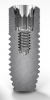
Among the factors affecting the fit of components in the implant-crown complex (eg, implant screw, final abutment) are the implant connection interface and interface issues with different implant tapers, angles, or tolerances. Original implant geometry included an external hex connection (Figure 1), which reports have shown can be prone to microgaps, fatigue, and frequent screw loosening.3 Trilobe connections, which are ideal for strength but require one of the lobes to be positioned mid-buccal for the abutments to function properly, were introduced later (Figure 2). The three lobes incorporated into the design of these connections are intended to withstand the stress of the implant and collar area.4
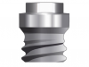
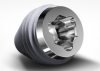
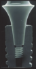
The third implant geometry—and the one most commonly used today—is the internal hex connection (Figure 3).5 There are also conical connections, which require a jig and indexing when orienting the abutment/crown onto the implant (Figure 4). Conical-hex combinations incorporate an internal hex for orienting or indexing the abutment (eg, Morse taper), ultimately producing a very strong connection that is easy to achieve (Figure 5).4,5 The interface between a conical or hex connection and the abutment greatly affects the mechanical tolerances of the implant/abutment/crown complex regarding fit, cyclic fatigue, and preload.
Mechanical tolerances mandate adherence to stringent requirements when restoring the implants, as well as when selecting components for use in the implant/abutment/crown complex. Published physical properties and success rates of implant systems are relevant to only those implants and components evaluated and tested in combination with each other.4,6 Therefore, the value and predictability of components of the implant/abutment/crown complex, as demonstrated through laboratory and clinical testing, may not be transferable to seemingly similar products—or even the same products—if they are placed with other implants or components not specifically manufactured with the same materials, under the same conditions, and according to the same performance parameters.3,5
Manufacturers of authentic and integrated implant system components determine the requirements for restoring their implants based on rigorous testing of their specific implant designs to confirm the mechanical tolerances necessary for long-term success, such as proper fit and ideal preload. When their basic abutment or implant designs are altered in some way by third parties and marketed as compatible solutions, deviations from what the original manufacturer intended may be present, such as length of the abutments or implant channel, which could result in a departure from the original accuracies reported.7 For example, because the length of the abutments and the implant channel critically affect fit, which subsequently impacts preload and cyclic fatigue, using aftermarket or inauthentic implant components could lead to long-term problems with treatment, including abutment/crown loosening, screw loosening, screw breaking, abutment fractures, implant fractures, or crestal bone loss.6-8
Implant Preload
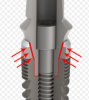
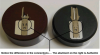
Implant preload is the axial or tensile force generated when an implant screw is torqued; approximately 90% of the torque is required to overcome the friction created by the threads of the screw, by the threads of the implant, and under the head of the screw that usually engages the bottom of the abutment.4 The remaining 10% of the torque (eg, 30 Nc or 35 Nc) is converted into the tensile or clamping force of the system that is necessary to hold the abutment onto the implant (Figure 6).
After preload is established, elastic deformation (ie, stretching and physical change below proportional limits) of the implant and abutment materials—whether gold, titanium, or other—occurs due to the applied torque, as well as stress from the pressure or load.4,6 The implant and component materials will return to their original shape after removal of the load. Elastic deformation is considered and accounted for in the design and manufacture of authentic integrated implant system components and typically does not result in detrimental sequelae. Achieving the appropriate preload and proper elastic deformation is critical for an intimate connection between the implant and the abutment and, therefore, preventing microgaps and bacterial infiltration that could lead to peri-implant hard- and soft-tissue complications.9-11
If a material is stretched above its proportional limits, it is termed plastic deformation. In implant dentistry, plastic deformation could occur by overtightening an abutment screw with too much torque, leading to cross-threading, stripping, or abutment and crown loosening, which could ultimately affect the fit and function of the implant/abutment/crown complex.4 Implant blossoming (ie, the collar fractures and expands outward, creating the appearance of a blossoming flower) could also occur, in addition to the previously cited formation of microgaps, which have been associated with higher bacterial activity in the perio-implant sulcus and crestal bone loss.2,12,13 However, the stronger the material, the higher its proportional limit.6
Microgaps
Microgaps are defined as the amount of space between an implant and an abutment and have been shown to be a determining factor in the potential for implant/abutment failure. The greater the microgap, the greater the likelihood for fracture, cyclic fatigue, and ultimate failure.7,8,12 Microgaps have also been observed in the screw thread interface with the implant abutment, particularly when aftermarket or so-called compatible solutions are used that do not have the requisite tolerances intended for the selected implant. In such instances, elastic deformation becomes plastic deformation across threads or strips; either situation can present negative consequences for implant restorations.
For example, when an aftermarket abutment claimed to be compatible is used with an implant (Figure 7), compared with the use of an authentic abutment intended for the implant complex (Figure 8), noticeable differences in abutment shape and microgaps between the two are commonly observed. Such discrepancies typically result from reverse engineering processes that do not achieve the expected dimensions, strength, or tolerances that the manufacturers of the authentic implant systems engineered into their design.4,7,8
Cyclic Fatigue
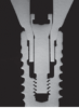
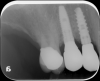
Cyclic fatigue can occur with dental implant complex components, including those that are authentic and fabricated by the original manufacturer. Defined as the accumulated stress that occurs as the result of repeated loads, which can ultimately lead to cracks, damage, and failure (even if the load is below a material’s or component’s proportional limits), cyclic fatigue can lead to problems with implants, implant/abutment interfaces (such as fractures at the implant/abutment connection) (Figure 9), and peri-implant hard and soft tissues.14-18
Visualizing Differences Between Authentic and Aftermarket Components
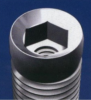
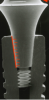
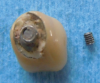
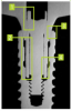
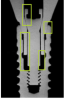
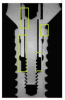
Authentic implant components that are made for each other demonstrate an intimate contact, as facilitated by both the proper channel length and ideal engagement of the taper in relation to the implant/abutment screw (Figure 10). Conversely, when aftermarket implant components are used, microgaps are visible, likely because the channels are not long enough or because there are gaps between threads that prevent proper torquing and achieving ideal preload (Figure 11 and Figure 12).
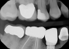
The presence of dark spaces, even from a cross-sectional photographic view, may indicate that an aftermarket part was used (Figure 13). Radiographically, everything should appear intimately tight against the implant interface (Figure 14). A visually absent intimate connection may indicate that the abutment/restoration and implants are incompatible (Figure 15).
Conclusion
The use of authentic integrated implant system components is critical for ensuring a precise fit between the abutment and the implant, preventing microgaps and avoiding unpredictable, negative sequelae that could affect implant treatment outcomes. When aftermarket and implant parts are intermixed, the integrity of multiple aspects of the implant treatment may be compromised. It is therefore incumbent on clinicians to be specific in their laboratory prescriptions and request genuine, integrated components designed and engineered for the implant system being placed. Implant manufacturer representatives can provide confirmation of laboratories using their products, and clinicians can request that laboratories provide the original packaging from the implant parts that have been used when delivering the case. A final radiograph can help to determine whether there could be an issue with the implant/abutment interface in the future due to the placement of a potential aftermarket component.
References
1. Krishnan V, Tony Thomas C, Sabu I. Management of abutment screw loosening: review of literature and report of a case. J Indian Prosthodont Soc. 2014;14(3):208-214.
2. Doolabh R, Dullabh HD, Sykes LM. A comparison of preload values in gold and titanium dental implant retaining screws. SADJ. 2014;69(7):316-320.
3. Gracis S, Michalakis K, Vigolo P, et al. Internal vs. external connections for abutments/reconstructions: a systematic review. Clin Oral Implants Res. 2012;23(suppl 6):202-216.
4. Hurson S. Use of authentic, integrated dental implant components vital to predictability and successful long-term clinical outcomes. Compend Contin Educ Dent. 2016;37(7):450-455.
5. Wiskott HW, Jaquet R, Scherrer SS, Belser UC. Resistance of internal-connection implant connectors under rotational fatigue loading. Int J Oral Maxollfac Implants. 2007;22(2):249-257.
6. Fernández M, Delgado L, Molmeneu M, et al. Analysis of the misfit of dental implant-supported prostheses made with three manufacturing processes. J Prosthet Dent. 2014; 111(2):116-123.
7. Zanardi PR, Costa B, Stegun RC, et al. Connecting accuracy of interchanged prosthetic abutments to different dental implants using scanning electron microscopy. Braz Dent J. 2012;23(5):502-507.
8. Gigandet M, Bigolin G, Faoro F, et al. Implants with original and non-original abutment connections. Clin Implant Dent Relat Res. 2014;16(2):303-311.
9. Jörn D, Kohorst P, Besdo S, et al. Influence of lubricant on screw preload and stresses in a finite element model for a dental implant. J Prosthet Dent. 2014;112(2):340-348.
10. Canullo L, Penarrocha-Oltra D, Soldini C, et al. Microbiological assessment of the implant-abutment interface in different connections: cross-sectional study after 5 years of functional loading. Clin Oral Implants Res. 2015;26(4):426-434.
11. Ricomini Filho AP, Fernandes FS, Straioto FC, et al. Preload loss and bacterial penetration on different implant-abutment connection systems. Braz Dent J. 2010;21(2):123-129.
12. Sui X, Wei H, Wang D, et al. Experimental research on the relationship between fit accuracy and fracture resistance of zirconia abutments. J Dent. 2014;42(10):1353-1359.
13. Pieri F, Aldini NN, Marchetti C, Corinaldesi G. Influence of implant-abutment interface design on bone and soft tissue levels around immediately placed and restored single-tooth implants: a randomized controlled clinical trial. Int J Oral Maxillofac Implants. 2011;26(1):169-178.
14. Berberi A, Maroun D, Kanj W, et al. Micromovement evaluation of original and compatible abutments at the implant-abutment interface. J Contemp Dent Pract. 2016;17(11):907-913.
15. Gratton DG, Aquilino SA, Stanford CM. Micromotion and dynamic fatigue properties of the dental implant-abutment interface. J Prosthet Dent. 2001;85(1):47-52.
16. Genna F. On the effects of cyclic transversal forces on osseointegrated dental implants: experimental and finite element shakedown analyses. Comput Methods Biomech Biomed Engin. 2003;6(2):141-152.
17. Dittmer MP, Dittmer S, Borchers L, et al. Influence of the interface design on the yield force of the implant-abutment complex before and after cyclic mechanical loading. J Prosthodont Res. 2012;56(1):19-24.
18. Blum K, Wiest W, Fella C, et al. Fatigue induced changes in conical implant-abutment connections. Dent Mater. 2015;31(11):1415-1426.