You must be signed in to read the rest of this article.
Registration on CDEWorld is free. Sign up today!
Forgot your password? Click Here!
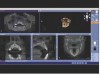
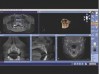
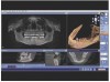
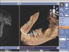
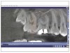
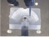
Cone-beam computed tomography (CBCT) and 3-dimensional (3D) imaging provide dentists with diagnostic information that had previously been unattainable, if not unimaginable (eg, connection between the teeth and the sinus; absolute thickness of jaw, bone, and mucosa), with conventional radiography (Figure 1 and Figure 2).1 As a result, CBCTs are now essential tools in implant dentistry because the information they provide can be interpreted, manipulated, and applied to prosthetically driven implant treatment planning.2 When combined with innovations in imaging, treatment planning software, and digital/computerized manufacturing (eg, CAM, 3D printing), CBCT scans facilitate more collaborative and enhanced implant treatment planning, in addition to fabrication of the tools for guided implant placement surgical procedures (eg, surgical stents).3
Among the conventional methods for treatment planning implant cases have been intraoral, panoramic, and cephalometric radiographic imaging techniques.4 Unfortunately, because these approaches are limited to providing 2-dimensional (2D) images of the anatomy, they cannot ensure thorough evaluation.5 Adequate bone height and width cannot be assessed properly with 2D images, and these anatomical characteristics are significant for determining implant length, position, and angulation.5
CBCT imaging, on the other hand, provides detailed 3D views of the oral anatomy that enable dentists to thoroughly assess bone density, height/width, alveolar nerve location, lingual concavity, and other landmarks with greater precision.6-9 This information can then be used for implant treatment planning, particularly determining implant size, length, placement location, and angulation.10
In fact, with the advent of treatment planning software, dentists can select the most appropriate implant for a case and place it exactly where it belongs, based on detailed 3D diagnostic, anatomical information. Additionally, the same types of techniques incorporated into the CAD process for creating digital restorations (eg, considering opposing and adjacent teeth, accounting for preparation angles and margins) can be applied to implant selection (eg, tissue level, implant shape), placement (eg, at the crest of bone, subcrestal), and subsequent restoration (eg, proper contours, ideal emergence profile).11 This dramatically reduces unknown and any associated liabilities, and facilitates a more efficient and predictable placement procedure. With implant planning software, all of the possibilities, potential obstacles, and limitations that could affect a particular case become obvious when viewed, analyzed, and planned in three dimensions.12
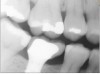
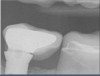
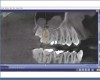
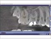
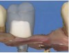
Interestingly, some concepts that are relevant to planning implant cases (eg, two adjacent teeth with too much distance between them; margins not prepared with sufficient depth, making it difficult to achieve a good contact or contour) (Figure 3 and Figure 4) are the same as factors that are important to planning restorative cases. Just as restorative dentistry requires anticipation and planning of ideal margin placement and contour development, implantology mandates identifying ideal implant location for proper placement in order to accommodate restorative needs (eg, emergence profile, contour, contacts with adjacent teeth, fixture/abutment placement, and angulation).2 Therefore, by pre-planning implant position in relation to the adjacent teeth, as well as determining the most suitable abutment type (eg, stock or custom), restorations can be fabricated to establish ideal margins and contacts and avoid inherent problems when too much space exists between teeth (Figure 5 and Figure 6).3
Although digitally planning ideal implant location, position, and angulation is important, ensuring it is ultimately achieved during the surgical procedures is a requisite for treatment success. Traditionally, radiographic images have been used as the basis for handmade drill guides for implant placement. However, these guides often could not account for proper implant depth and were prone to the inconsistencies inherent with analog fabrication methods.13 With the advent of CBCT imaging and treatment planning software, anatomical information can be incorporated into the implant placement and restorative plan, and more precise, CAM-fabricated surgical stents produced.14,15 Such patient-specific, computer-generated and machined surgical stents allow dentists to place implants more accurately and efficiently, at the proper location and angulation, and to the proper depth.13-15
Prosthetically and Surgically Balanced Implant Placement
Utilizing CBCT images, implant treatment planning software, and dental CAD software for restoration design does more than enable pre-planning of the exact implant location and angulation, along with the restoration design (eg, shape, color, contours, emergence profile, etc), before any surgery or restorative work is performed. Rather, it also supplements attempts to mimic nature through material selection (ie, replicate dentin or enamel compressive strength; compatibility of tensile strengths). In essence, the combined use of these technologies allows for prosthetically driven implant placement that facilitates greater functionality and stability of implant treatments. Such digital workflows have demonstrated high accuracy for virtually planned implants with a guided, flapless placement.12
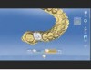
For example, by virtually seating an implant restoration in the context of the implant location—and visa versa—and then drawing a line through the center of the proposed restoration (Figure 7), it becomes easier for the dental team to complete restorative treatment. Proper implant angulation can be determined, and a surgical stent subsequently milled or 3D printed to guide precise surgical procedures. This helps to avoid damaging such anatomical landmarks as the inferior alveolar nerve canal, or impinging on the roots of adjacent teeth. Instead, the surgery will exactly replicate what is designed and pre-planned.
However, there are certain situations, particularly in the anterior, where prosthetic solutions alone would eliminate or negate the ability to place an implant or a fixture in that area, especially in the absence of consideration of the surgical needs of the case. One such scenario is if a screw-retained implant were planned for a mandibular first molar, where the fixture might need to be angled such that it would perforate the buccal bone, subsequently requiring extensive grafting on the facial (Figure 8). Ridge augmentation would be needed, and the apex of the implant would require significant angulation to allow the top of the implant to draw the restoration.
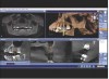
Therefore, many factors must be balanced when planning implant cases (eg, surgical limitations, prosthetic requirements), and margin position is among the critical considerations for implant placement and subsequent restoration. For example, in a case involving the maxillary first and second molars, CBCT axial views can illustrate the shape of the teeth, as well as the position of the second molar at the crest of bone, with normal occlusion, no super-eruption, and no issues of tilting or tooth malalignment (Figure 9). The distance between the tooth walls is approximately 1.5 mm, right above the crest of bone. Using the CBCT and implant planning software, the implant can be plotted at the tooth site.
However, it is important to understand that what is being planned is a cylindrical-shaped structure (ie, implant), which is placed right at the crest of the bone; the top of the implant and the cylinder do not mimic what a second molar actually looks like (Figure 10). If an implant is placed in this manner, as opposed to having the margins flush with where actual tooth contours are, then it will be difficult to achieve the appropriate contacts. An alternative view illustrates the implant placed at the crest of bone, leaving substantial space that would preclude creating the ideal emergence profile to the mesial (Figure 11). Continuing the planning by digitally adding a prefabricated abutment emphasizes the margin location. Combined with the proposed implant placement at the crest of bone, developing an emergence profile from that margin would result in a “potbelly” restoration.
Conversely, moving the entire implant/abutment complex to the mesial—essentially ignoring the distal—may initially appear to create the perfect abutment margin placement, simply by moving the implant position (Figure 12). Unfortunately, although moving to the mesial would enable a more ideal emergence profile, a compromised distal aspect would result; a large cantilever, very large unsupported ceramic, or very large abutment would remain on the distal aspect.
Alternatively, moving the entire implant/abutment complex that created challenges in the molar region over to the premolar area now places the margins in the perfect location for developing the emergence profile (Figure 13). From a radiographic perspective, it blends well with the natural teeth.
The Digital Implant Treatment Planning Process
Combining prosthetically driven needs with surgical needs becomes easier when integrating a digital implant treatment planning process. This enables control and evaluation of all aspects and components of the treatment (eg, implant and abutment selection, implant placement, margin location, tissue contours, contacts). Sufficient space can be planned to accommodate an abutment that, once the soft tissue has been properly contoured and shaped, will allow margin placement right at the gumline or 0.5 mm above the gumline for easy clean-up and flossing of excess cement (Figure 14).
After reviewing a patient’s CBCT scans, the digital implant treatment planning process begins by creating a digital model of the patient’s intraoral condition. This can be obtained by taking a digital intraoral impression, or by making a traditional analog polyvinyl siloxane impression, pouring a conventional stone model, and then CBCT scanning it to convert it to a digital model.
Using the digital model as a basis, the anticipated restoration is planned, mapped out, and otherwise designed using CAD software (Figure 15). This digital wax-up is used to essentially draw the restoration and place the margins exactly where they need to be to establish the ideal emergence profile. This prosthetic plan will help to determine subsequent implant placement and angulation.
Next, to plan the implant placement, two digital files (ie, CBCT scan and digital restoration wax-up) are merged together in relation to each other (Figure 16). By incorporating the designed restoration into the CBCT at the site location, the software can be used to plot the precise implant location and angulation. Lines and indicators are drawn through the center of the proposed restoration to indicate implant position, depth, width, etc. Once the implant placement plan is complete, this combined surgical/prosthetic digital file provides the information from which the surgical stent will be fabricated via 3D printing or CAM processing (Figure 17).
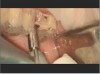
During the surgical appointment, every step of the procedure (ie, drilling, implant placement) will be fully guided through the surgical stent to ensure that the outcome most closely replicates what was treatment planned. A tissue punch or flap procedure is performed, after which the surgical stent is fitted into the patient’s mouth and properly held in place (Figure 18). The stent includes a sleeve that is perfectly positioned to stop the implant drills when they reach the intended depth; note that the sleeve is coordinated to work with the appropriate set of drills to be used with the implant system selected (Figure 19).
After drilling with the surgical stent in place and the proper series of drills, the implant is placed in the exact position that was planned (Figure 20). Performing this type of procedure using a pilot drill and pilot stent, which may require removal of the stent and subsequently freehanding the remainder of the procedure, could lead to placement discrepancies and/or miscalculations.
Conclusion
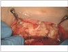
The advent of digital implant treatment planning and the ability to fabricate surgical guides has completely changed one of the most difficult procedures in dentistry, one that has been the hardest to perform and required the most amount of training. Although it is always advisable to refer out cases that are more complicated or complex than the doctor’s comfort level, 3D implant planning and guided surgery have made the procedures associated with exact placement of implants simpler and more predictable (Figure 21 and Figure 22). When implants are prosthetically driven and accurately placed, realizing ideal implant restorations also becomes easier.
ABOUT THE AUTHOR
Armen Mirzayan, DDS
Private Practice, Los Angeles, California
REFERENCES
1. Katsoulis J, Enkling N, Takeichi T, et al. Relative bone width of the edentulous maxillary ridge. Clinical implications of digital assessment in presurgical implant planning. Clin Implant Dent Relat Res. 2012;14 suppl 1:e213-e223.
2. Mora MA, Chenin DL, Arce RM. Software tools and surgical guides in dental-implant-guided surgery. Dent Clin North Am. 2014;58(3):597-626.
3. Arunyanak SP, Harris BT, Grant GT, et al. Digital approach to planning computer-guided surgery and immediate provisionalization in a partially edentulous patient. J Prosthet Dent. 2016;116(1):8-14.
4. Harris D, Buser D, Dula K, et al. E.A.O. guidelines for the use of diagnostic imaging in implant dentistry. A consensus workshop organized by the European Association for Osseointegration in Trinity College Dublin. Clin Oral Implants Res. 2002;13(5):566-570.
5. Garg AK, Vicari A. Radiographic modalities for diagnosis and treatment planning in implant dentistry. Implant Soc. 1995;5(5):7-11.
6. Wöhrle PS. Predictably replacing maxillary incisors with implants using 3-D planning and guided implant surgery. Compend Contin Educ Dent. 2014;35(10):758-768.
7. De Oliveira RC, Leles CR, Normanha LM, et al. Assessments of trabecular bone density at implant sites on CT images. Oral Surg Oral Med Oral Pathol Oral Radiol Endod. 2008;105(2):231-238.
8. Eufinger H, König S, Eufinger A, Machtens E. [Significance of height and width of the alveolar ridge in implantology in the edentulous maxilla. Analysis of 95 cadaver jaws and 24 consecutive patients]. Mund Kiefer Gesichtschir. 1999;3 suppl 1:S14-S18.
9. Salimov F, Tatli U, Kürkcü M, et al. Evaluation of relationship between preoperative bone density values derived from cone beam computed tomography and implant stability parameters: a clinical study. Clin Oral Implants Res. 2014;25(9):1016-1021.
10. Mello LA, Garcia RR, Leles JL, et al. Impact of conebeam computed tomography on implant planning and on prediction of implant size. Braz Oral Res. 2014;28:46-53.
11. Kourtis S, Skondra E, Roussou I, Skondras EV. Presurgical planning in implant restorations: correct interpretation of cone-beam computed tomography for improved imaging. J Esthet Restor Dent. 2012;24(5):321-332.
12. Barros Vde M, Costa NR, Martins PH, et al. Definitive presurgical CAD/CAM-guided implant-supported crown in an esthetic area. Braz Dent J. 2015;26(6):695-700.
13. Greenberg AM. Digital technologies for dental implant treatment planning and guided surgery. Oral Maxillofac Surg Clin North Am. 2015;27(2):319-340.
14. Klein M, Abrams M. Computer-guided surgery utilizing a computer-milled surgical template. Pract Proced Aesthet Dent. 2001;13(2):165-169.
15. Klein M, Cranin AN, Sirakian A. A computerized tomography (CT) scan appliance for optimal presurgical and preprosthetic planning of the implant patient. Pract Periodontics Aesthet Dent. 1993;5(6):33-39.