You must be signed in to read the rest of this article.
Registration on CDEWorld is free. Sign up today!
Forgot your password? Click Here!
GLOSSARY
Absorption – transfer of some or all of x-ray photon energy to material or matter; dependent on the energy of the x-ray beam and composition of the absorber
ALARA – safety principle that states that radiation exposure should be kept to a minimum or as low as reasonably achievable
Algorithm – computer-adapted mathematical calculation applied to raw data during image reconstruction
Analog data – data characterized by a continuous grayscale from black to white
Analog to digital converter (ADC) – device that converts the analog output signal into numeric data based on the binary number system of 0 and 1; the voltage of the output signal is measured and assigned a number from 0 (black) to 255 (white) according to the intensity of the voltage
Area array – matrix or layout of pixels in columns and rows; format for intraoral direct digital receptors
Back up – copying files from the hard drive to another medium, such as compact disks, to store files and use in the event that data is lost
Binary number system – computer language in which two digits, 0 and 1, are used to represent information
Bit – binary digit, smallest unit of information that a computer is able to recognize and represent in the form of 0 or 1
Brightness – digital equivalent to density or overall degree of image darkening
Bytes – group of eight bits that represents one character or digit; the number of possible bytes in computer language is 28 or 256
Bus – path the computer uses to transfer data
Cephalometric radiography – extraoral images of the skull accomplished by use of a head positioning device or cephalostat, typically 8” x 10” projections; the lateral head plate is a common view used in orthodontic evaluation
Charge coupled device (CCD) – solid-state, silicon chip detector that converts light or x-ray photons to electrons
Collimation – device used to restrict the size and shape of the x-ray beam
Complimentary metal oxide sensor (CMOS) – solid-state detector similar to the CCD with built-in control functions, smaller pixel size and lower power requirements
Complimentary metal oxide sensor active pixel sensor (CMOS-APS) – CMOS detector with active amplifying transistors integrated in each pixel to decrease noise and improve signal output
Contrast – the difference in densities between various areas on a radiographic image; high contrast images have few shades of gray between black and white while low contrast images will demonstrate more grays
Contrast resolution – the ability to differentiate small changes in density as displayed on an image
Data compression – method of storing data in a way that requires less space or memory
Density – overall degree of blackness or image darkening of an exposed film; comparable to brightness in digital imaging
DICOM (Digital Imaging and Communications in Medicine) – standard with detailed specifications that describes a method of formatting and exchanging digital images and related information; standard applies to the operation of the interface used to transfer data in and out of an imaging device
Digital image – a video image in pixel format that can be stored in the computer memory for processing
Digitization – conversion of an incoming analog signal into a digital or numeric value for storage and processing
Direct sensor – receives radiation directly like film and deposits the energy in the electron wells or picture elements
Distance and position rule – radiation safety rule in which the operator stands 6’ from source of x-rays and positioned between 90° - 135° angle to the primary beam to minimize occupational exposure
Dpi (dots per inch) – method of measuring the density output of scanners and printers; the greater the dpi, the better the resolution of the printed image
Dynamic range – the numerical range of each pixel; in visual terms it refers to the number of shades of gray that can be represented
Edge – borders between regions of an object
Electron well – individual pixel into which x-ray or light energy is deposited during x-ray exposure of CCD or CMOS detectors
Fiber optics – thin transparent fibers of glass or plastic material that transmit light throughout their length by internal reflection
Filtering – analog or digital image processing used to enhance or modify an image
Focal spot – anode tungsten target where x-rays are generated; focal spot size should be as small as possible in the range of .5 to 1.5 mm2; the size has an influence on image quality in terms of sharpness and geometric distortion
Gigabyte (GB) – unit of computer storage equivalent to a billion bytes
Gray level – measure of image brightness or intensity in a range between black and white
Hard drive – hardware that contains the hard disk or storage disk inside the computer
Hardware – the physical parts or components of the computer system
Histogram – graphic representation of the frequency of each gray value that appears in the image
Histogram equalization – modification of the histogram to evenly distribute a narrow range of gray levels across the entire available range
Image processing – an operation used to improve, correct, analyze or alter an image
Image enhancement – image processing operations that alter the visual appearance of the image; typical enhancement tools include density, contrast, colorization, and various filters
Image matrix – the layout of cells in rows and columns with each cell corresponding to a specific location and representing the brightness or intensity in that location
Indirect sensor – receptor that receives x-rays upon exposure and stores the energy until released via a scanning process
Intensity – the relative brightness of part of an image
Kilovoltage – (kV) potential difference between the anode and cathode in an x-ray tube; it controls the quality or penetrating power of the x-ray beam
Latitude – measure of the range of exposures that will produce usefully distinguishable densities on a film
Linearity – linear or direct relationship between exposure and image density; contrast is not affected but density can be altered after image acquisition
Linear array – a solid-state detector that consists of a single row of pixels; used in direct digital extraoral imaging
Line pair – a bar and its interspace of equal length; used to quantify the resolution of an image
Lossy – storage method in which some data is lost but the compressed file is still capable of producing a diagnostically acceptable image
Lossless – storage method in which no information is lost in the compression of a file
Memory – high speed, large capacity storage in the computer where data and images are stored and retrieved
Network – method of connecting several computers so that they interact with each other and information can be accessed and displayed at any workstation in the network
Noise – unwanted or irrelevant information that interferes or undermines diagnostic information
Operating system (OS) – computer system that links the computer with the user
Output – processing of transferring information from primary memory to storage or the user
Photon – electromagnetic radiation in the form of x-rays and gamma rays that interact with matter like a particle or small bundle of energy rather than a wave
Photostimulable phosphor plate (PSP) – polyester base coated with a crystalline halide emulsion; the plate converts x-ray energy into stored energy that is released when scanned with a helium-neon laser beam
Photostimulation – emission of visible light after excitation by a laser light beam
Photomultiplier tube – electron tube that converts visible light into an electrical signal
Pixel – picture element; individual cell of the image matrix in which the value of cell determines brightness
Primary barrier – protective barrier adequate to absorb the primary or useful beam
Ram (random access memory) – temporary memory of the computer in which programs and information are stored
Receptor – any device or medium that transforms x-ray energy into latent images that can be made visible by processing
Resolution – measures how well a radiographic image reveals small objects that are close together; measured in line pairs per millimeter
Sharpening – computer operation that enhances edges
Sharpness – ability of a radiographic image to define an edge or display density boundaries
Software – computer programs that tell the hardware what to do and how to store data
Spatial frequency – measure of resolution expressed in line pairs per millimeter
Spatial resolution – measure of the extent that the displayed image appears identical to the original analog image; determined by the number and size of the pixels used to compose the displayed image
Storage phosphor – another term or name for photostimulable phosphor plate receptors
Subtraction – computer processing technique that subtracts information from pre- and post-radiographic images by removing all unnecessary structures and enhancing areas of interest or change
Teleradiography – the process of remote transmission and viewing of digital images
Template – a pattern or format used to create a document or file that is similar but may have some small differences
USB (universal serial bus) – hardware bus standard that permits the user to plug a peripheral into a USB port and have it automatically configured for use
Workstation – desktop computer system often connected to larger computer systems to allow users to transfer and share information
X-rays – a form of electromagnetic radiation with wavelengths shorter than visible light with abilities to penetrate, ionize and produce a latent image
INTRODUCTION
Technology supporting digital dental radiology began in France in 1984. An article describing direct digital imaging technology was first published in US dental literature in 1989.1 Since then, digital imaging technology has evolved with improvements in sensor design, computer software, hardware packages, and technical support. The following course will provide a foundation for understanding digital imaging technology, necessary equipment, digital imaging receptors, technique, acquisition, enhancement, transfer, and storage. Comparisons with film-based imaging as well as the diagnostic utility of digital images will be discussed.
DIGITAL RADIOGRAPHY
Equipment Requirements
Digital imaging utilizes computer technology and digital receptors for the acquisition, viewing, enhancement, storage, and transfer of radiographic images. Essential components include an x-ray machine capable of producing small increments of radiation, a computer and monitor with appropriate hardware, software, and printing capabilities, an analog-to-digital converter, and a digital sensor.
In some instances, older x-ray equipment may need to be replaced in order to achieve the lower exposure settings used for digital radiography. X-ray units recommended for use in digital radiography should have the following characteristics: the smallest focal spot possible, an accurate timer capable of producing very short exposures, direct current with 70 kV setting or below, and 5 mA or less and rectangular collimation.2 Technical specifications vary among manufacturers but typical minimum requirements include an Intel® Core™ i3/i5 processor with Microsoft® Windows® operating system (8 Pro, 7, XP Pro, Vista), 2 GB RAM and 250 GB of hard disk drive, minimum CRT with .28 dot pitch @ 800 x 600 or flatscreen LCD with 400:1 contrast ratio @ 1024 x 768, USB 2.0 port and Intel® chipset and database server (MSDE SQL Server 2000 or SQL Server Express).3-6
Daily back-up of digital data is recommended. Other peripherals may be needed or desired depending on the digital system selected, network set-up, and accessories that the clinician may want to supplement the imaging capabilities.
The optimal application of digital technology in the dental practice setting is to have a networked office system that is paperless and integrates all aspects of the patient record, including medical and dental history information, digital radiography, intraoral camera and cosmetic dentistry imaging, with patient education and entertainment resources, as well as billing capabilities.
When new technology such as digital radiography is implemented in the office, it is important that all members of the office staff are committed to the change, receive training, and have an opportunity to prepare and practice before utilizing the technology on patients. This will make the transition smoother, allow clinicians to gain confidence and competence with the new technology and be able to present it in a positive and enthusiastic manner to patients.
Advantages and Disadvantages
Digital radiography is a very attractive alternative to film-based imaging. One of the most commonly cited positive features is radiation dose reduction. Intraoral imaging dose reduction is dependent on the particular film speed used, number of images taken, beam collimation and the number of retakes. Intraoral digital image receptors provide equal or greater dose reduction compared to F speed film.7 Greater dose reduction can be achieved when retakes were eliminated and the number of additional images is limited.8 There is no significant dose reduction in extraoral digital imaging when digital systems are compared to high-speed film and rare-earth screen combinations.7,9
Other obvious benefits include the elimination of the darkroom, processing chemistry and the errors associated with improper darkroom maintenance, chemical handling, solution replenishment and replacement. Several studies have indicated that improper processing is the most significant contributor to retakes in film-based imaging.10,11 Additional advantages include the ability to view the image more quickly, enhance the captured image as well as the ease of storage, retrieval, duplication and transmission.12,13 Digital receptors are reusable but may require replacement if mishandled or damaged. Adoption of digital technology presents the office in a positive light and infers that the dentist and supportive dental health professionals are up-to-date with current trends in dentistry.
The major disadvantages of digital radiography include the cost of the systems and their set up, susceptibility of some receptors and/or components to damage, high receptor replacement costs and other issues related to a relatively new industry such as system obsolescence or manufacturer’s going out of business.8,12 Manufacturers of digital imaging systems continue to address these concerns and have made progress in these areas. Spatial resolution has also been cited as a disadvantage of digital imaging when compared to film. Theoretically, the spatial resolution of digital imaging systems ranges between six and twenty-six line pairs per millimeter (lp/mm) compared to more than 20 lp/mm for film.14 However, the actual resolution is typically lower due to noise and other aspects in signal transfer and image production.12 PSP systems have lower spatial resolution than solid-state digital detectors and the more recent CMOS detectors appear to have higher spatial resolution than CCD detectors.8 In addition, there are certain features of intraoral sensors that make them less desirable than film in terms of infection control and placement inside the mouth. These particular aspects will be addressed in the next section.
Intraoral Digital Radiography
Digital imaging is very similar to film-based imaging in that it requires x-ray interaction with a receptor, latent image processing and subsequent viewing of the image. In digital imaging, the receptors are highly sensitive sensors that require considerably less radiation exposure than film. The data acquired by the receptor is analog data in the form of a continuous gray scale and must be converted to digital data to be useful. The ADC or analog-to-digital converter transforms analog information into numerical information based on the binary number system. Computers operate on the binary number system in which two digits (0 and 1) are used to represent data or information. These two characters are called bits (binary digit) and they form words eight or more bits in length termed bytes. The total number of possible bytes for 8-bit language is 28 = 256. The voltage of the output signal is measured and assigned a number from 0 (black) to 255 (white) according to the intensity of the voltage. These numerical assignments translate into 256 shades of gray. Some digital systems sample the raw data at a resolution of more than 256 gray values such as 10 bit or 12 bit values but are reduced to 256 shades of gray.15 Once the computer processes the data, the image appears on the monitor for interpretation, enhancement and subsequent storage.
Intraoral Digital Receptors
Digital radiography receptors include “direct” and “indirect” receptors. Direct receptors communicate with the computer through an electronic cable, although a wireless sensor system is available that transfers data through a radiofrequency transmitter. Indirect receptors require a scanning step.
Direct Receptors—The charge-coupled device (CCD), complimentary metal oxide semiconductor (CMOS), and the complimentary metal oxide semiconductor active pixel sensor (CMOS-APS) are all direct receptors. These receptors are rigid, solid-state detectors made of silicon that are arranged in an array of x-ray or light sensitive pixels (Figure 1). All three of these sensors use similar technology with differences in power requirements, internal components, charge transfer and manufacturability.16-18 Each pixel is approximately 40μ to 20μ15 in size and is configured into rows arranged in a matrix of 512 x 512 pixels. The pixel size varies depending on the digital receptor, and the size of the pixel has an influence on the image resolution. For example, a 40μ-50μ pixel size results in an image resolution of approximately 10 lp/mm to 11 lp/mm.16 Solid-state sensors used for intraoral imaging are area arrays with two basic formats, direct and fiberoptically coupled. Direct sensors capture the image directly like film while fiberoptically coupled sensors utilize a scintillation screen coupled to a CCD. When x-rays strike the screen material light photons are produced, detected and stored by the CCD. Direct sensors communicate with the computer via an electrical cable, although wireless sensors recently have been introduced for direct digital intraoral imaging. Direct sensors are available in sizes comparable to 0, 1, and 2 film but are thicker and more rigid in their construction. The active image area is smaller than film so the area of coverage is somewhat diminished. Direct detectors can be reused for each successive projection and the acquired image can be viewed almost instantaneously after exposure.
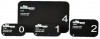
Indirect Receptors—Photostimulable phosphor plates (PSP), also known as storage phosphor plates (SPP), uses indirect receptors. PSP/SPP are flexible, wireless receptors that are similar in size and thickness to film (Figure 2). Phosphor plates are available in the same sizes as intraoral film including 0, 1, 2, 3, and 4. An individual plate must be used for each projection in the survey, just like film. The phosphor plates consist of a polyester base that is coated with a crystalline halide emulsion of a europium-activated barium fluorohalide compound.19 When x-rays interact with the phosphor, a latent image is formed and stored until the energy is released during a scanning process.
The plates must be carefully transferred and inserted into a scanning device in which a helium-neon laser beam is applied to release the energy in the form of light. The intensity of the emitted light is proportional to the amount of x-ray energy absorbed by the phosphor plate. The light is captured and intensified by a photomultiplier tube, which converts the light into an electronic signal. The analog-to-digital converter digitizes the data and displays the image on the computer monitor. Before the plates can be reused, the remnant energy must be removed or erased by exposure to intense light. This can be accomplished by exposing the plates to viewbox light, use of commercially produced devices, or by utilizing erasure features built into newer scanner models.
There are a number of phosphor plate systems available for digital imaging. Like direct sensors, the primary advantage is exposure reduction. In addition, PSP receptors have wider dynamic range and a larger active area, are thin and wireless, and can be used like film. As previously mentioned, the spatial resolution is lower than direct sensors and film,8,20 a processing step is required like film and, thus, image display is delayed. The time delay varies from seconds to minutes depending on the system and the type and number of projections taken. The plates require careful infection control and gentle plate handling to avoid image artifacts. A study conducted by Bedard et al21 investigated the durability of phosphor plates and the degradation of image quality due to emulsion scratches. They found that plate placement on the scanner drum had a significant impact on the number of scratches produced as did increased usage per plate.21 Therefore, the plates need to be checked for wear on an ongoing basis and may need to be replaced after 50 uses.21 However, Ergun et al22 determined that phosphor plates could be used confidently up to 200 times. Another study investigated the effects of different storage conditions and varying time intervals between exposure and scanning of the plates.23 Martins et al23 found that with one PSP system certain storage conditions and time delay in processing the plates resulted in loss of image density, which could have an impact on image interpretation. This impact was demonstrated in a study by Sogur et al24 in which plate scanning delays had a significant effect on pixel intensity degradation and the ability to detect occlusal caries.
Film-based images can be scanned to digitize radiographic information. Scanned radiographs are another form of indirect digital imaging. Since the scanning process produces a second version of the original image, some information is lost in translation. This technique requires an optical scanner that is capable of scanning at 600 dpi, able to process transparent images and has the appropriate software to produce the digital image.16,20 This method allows digitization of film-based radiographic images so that they can be stored and incorporated into the digital patient record when the dental office makes the transition from conventional to digital radiography. The radiographic images are then available for comparison to newly acquired images and all information is organized and stored in one source for retrieval.
Intraoral Technique
As with film-based imaging, the paralleling technique is the preferred method for acquiring intraoral digital images. Most digital imaging system manufacturers provide receptor instruments that accommodate their sensor size, allow placement inside the patient’s mouth, and conform to the principles of paralleling technique. Also, tab techniques may be used for bitewing radiography.
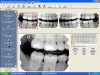
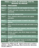
Infection Control—Typically, the receptor instruments can tolerate sterilization methods such as steam autoclaving before reuse. Digital receptors cannot be sterilized so the clinician must adhere to careful disinfection and barrier coverage techniques to avoid direct and cross-contamination of the receptor. The standard spray-wipe-spray or immersion disinfection technique is not appropriate for sensor preparation. Wiping rigid digital sensors with a mild disinfectant agent before barrier placement is thought to be an acceptable disinfection practice.25 When in doubt, refer to the manufacturer’s instructions regarding recommendations for sensor preparation and protection prior to use. PSP plates should be inserted into a barrier envelope and sealed before placement in the mouth. After removal, the barrier should be cleaned with disinfectant hand soap and water and then dried.26 Following glove removal and hand washing, the barrier should be opened carefully and the plate dropped out with the sensitive side down into transfer carrier.26 The clinician should be observant during the radiographic procedures to ensure that the barrier does not become torn during instrumentation. Table 1 presents the basic steps involved in intraoral digital imaging. An example of a patient file is depicted in Figure 3. The act of saving the image is similar to saving any file on a computer system.
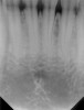
Common errors—As with any imaging technique, errors can be produced when the clinician fails to place the receptor properly or align the x-ray beam in the correct vertical and horizontal angulation or center the x-ray beam over the receptor. Therefore, it is possible to produce image foreshortening, elongation, overlapping, cone cuts, and inadequate coverage of the crowns or apices of the teeth (Figure 4). Ultimately, the technical quality of digital images as with film-based imaging is dependent on the skill of the clinician.
Several studies have identified some difficulties associated with the placement of rigid receptors. Versteeg et al27 found a significant increase in horizontal placement errors, especially in molar regions, and vertical angulation errors in the anterior segments that cut off the incisal edges of the teeth. Other studies have documented similar findings in horizontal placement and vertical angulation errors as well as cone cuts and difficulties with vertical bitewing placement resulting in missed structures and patient discomfort.28-30 Storage of phosphor plates present other image problems. Although the plates are flexible and thinner like film, they are susceptible to the production of image artifacts by abrading the emulsion during handling and erasure.21
Extraoral Digital Radiography
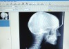
As with intraoral digital radiography, extraoral digital images can be acquired using direct or indirect digital imaging systems. Digital panoramic and cephalometric machines are available that utilizes either linear array CCD or CMOS detectors or PSP plate sensors. With CCD or CMOS extraoral imaging, conventional film is replaced by a long, vertical, rigid digital receptor a few pixels wide.31 With PSP receptors, the plate is configured in the same dimensions as panoramic or cephalometric film and can be placed directly into the cassette with the intensifying screens removed. As with intraoral direct digital imaging, a patient file must be created, the appropriate template or projection selected, patient positioned, exposure made, and image viewed on the monitor (Figure 5). With PSP plate receptors, the plate needs to be scanned before the image can be viewed. The technique for preparing and positioning the patient is similar to conventional panoramic and cephalometric radiography. In addition, errors can be produced when the patient is improperly prepared and the head alignment does not conform to technique requirements. The quality of the resulting image is ultimately the responsibility of the clinician and proper application of extraoral imaging techniques.
Both film-based and digital formats produce comparable images with spatial resolution of 3 lp/mm to 4 lp/mm for PSP receptors and 6 lp/mm to 8 lp/mm for CCD receptors.32 As with intraoral digital imaging, elimination of the darkroom, the ability to enhance9 and analyze the image,33 and the convenience of image storage, duplication, and retrieval are beneficial. With extraoral imaging, the file size is considerably larger than intraoral imaging and must be reduced by compression techniques that facilitate storage but do not compromise the diagnostic quality of the image.
Radiation Safety and Protection
Because x-rays remain the energy source for producing radiographic images whether film-based or digital, the clinician should still adhere to the radiation protection principle, ALARA, As Low As Reasonably Achievable. Although the dose of ionizing radiation to the patient is less than film-based imaging, protection principles for both the patient and operator should continue to be practiced. As usual, the patient should be shielded with a thyroid collar (for intraoral imaging only) and lead apron and the operator should stand at a remote position, whether behind an adequate primary barrier or at a 6’ distance and between a 90° to 135° angle to the x-ray beam.
Familiarity with the program software, proper handling of the receptor and adherence to technique guidelines will help the clinician avoid unnecessary retakes. Numerous retakes undermine the exposure reduction gained with digital imaging, and in many circumstances digital surveys equal the exposure of film-based imaging due to increased numbers of retakes. In a 2003 study conducted by Berkhout et al,34 it was concluded that general dentists using digital radiography were more inclined to take radiographic images than dentists using conventional radiography. Those who used solid state intraoral receptors took more images than PSP and film users.34 The most common reasons for taking more images were that digital imaging requires less exposure than film and for the purposes of error correction.34 In some cases the dose reduction was cancelled out by the increase in the number of images taken.34 The investigators determined that for solid-state receptor users who take 50% more radiographic images, the actual exposure reduction was closer to 25% than in the commonly reported range of 50% to 80% dose reduction.34 Several studies have indicated that the procedure for retaking digital images is so convenient that the clinician may be more inclined to repeat more exposures when compared to film.29,34
Imaging Processing
One of the advantages of digital imaging is that once acquired, the image can be changed and viewed in a variety of ways. Image processing is a computer operation that can be applied to improve, correct, analyze, or alter a digital image.35 Image processing can be broken down into different classifications: image enhancement, image restoration, image analysis, image compression, and image synthesis.35 The following discussion will focus on the most commonly used image processing tools: image enhancement, some aspects of image analysis, and image compression.
Image enhancement software operations are performed to change the visual appearance of the image. Common enhancements tools include: brightness and contrast adjustments; black/white reversal; pseudocolor application; sharpening; and zoom.
Adjustment of the brightness and/or contrast can salvage an image that would not be diagnostic if film-based. Ideally, digital receptors should be exposed at proper exposure settings. If the pixels are not over-saturated with radiation,20 it is possible to alter the brightness or density so that the image is readable. This can be accomplished through the addition or subtraction of the same value to each pixel.14 Contrast can be adjusted by altering the distribution of the gray levels in the image. This distribution is depicted in the image histogram, which displays the frequency of each gray value that appears in the image. Histogram stretching redistributes the original range of gray levels over the entire range without changing the image itself.35 The contrast can be adjusted to produce high contrast visualization, which is desirable in caries interpretation, and lower contrast, which may be desirable when looking for subtle changes in periodontal disease.36
Another option is to view structures by inverting or reversing the image so that radiolucent structures appear radiopaque and vice versa (Figure 6). This tool may be useful in visualizing the trabecular pattern of bone and pulp canal and chamber anatomy.
Pseudocolor enhancement converts the gray scale of the image into colors. The application of pseudocolors is not considered to be an effective tool to segment or view particular objects within the image.35 Although the application of color may be developed into a more useful tool in the future, its utility as an enhancement has not yet been demonstrated.20,37
Sharpening enhancements are utilized to better demonstrate edges and margins and are accomplished by various filtering techniques. Sharping may make images appear more appealing to the eye, but there is no scientific evidence that there is any actual improvement in the diagnostic quality of the image.38
The zoom feature allows magnification of any portion of the image to better view details. The window display allows the clinician to determine the zoom location by framing the area on the original image.
Digital subtraction is categorized as an image enhancement but will be presented as a separate topic in subsequent text.
Image analysis operations are used to acquire nonpictoral information from the image.35 Measurement is the most commonly used analysis operation in clinical digital radiography. Typical measurement tools include single or multiple linear measurements, angle determination, grid application, and calibration of known objects and their depiction on the image.39 Pixels can be measured individually or along a straight line in either vertical or horizontal histogram displays.39
Image compression is a process of file reduction. The purpose of image compression is to reduce computer storage space and facilitate image retrieval and transmission. Compression becomes a more important issue as the number of patient records and image files to be stored increases over time.
There are two types of image compression methods, lossless and lossy. Lossless compression retains all of the information in each pixel of the original image and essentially is identical to the image first acquired by the digital imaging system. Lossless compression algorithms provide a very limited degree of file reduction in the range of 1:235 to 1:340 ratio, approximately one-half to one-third reduction. Lossless compressed images require more memory to manipulate the image and longer transmission time to send an image to a remote site. Lossy compression affords higher compressibility but results in some loss of data. Lossy compression is accomplished through the division of the image into smaller blocks and selective discarding of data.40 Lossy compressed images require less memory to manipulate the image and the transmission time is reduced.
Joint Photographic Experts Group (JPEG) is a common compression protocol that can support both lossless and lossy compression.40 A number of research studies have investigated the extent that image files can be compressed and still be diagnostic. In 2002 Eraso et al40 determined that high compression ratios had a severe negative impact on the diagnostic quality of digital images in the detection of periapical lesions. The results of the study indicated that compression ratios lower than 1:32 can safely be used for diagnostic procedures in endodontics.
In another investigation of the effects of compression and the detection of chemically-induced periapical lesions, Koenig et al41 found no significant differences between compressed and original images at the level of 1:23 and 1:28 JPEG lossy compressions. With respect to caries diagnosis, Pabla et al42 studied the effects of compression on proximal caries detection. They concluded that Joint Photographic Experts Group File Interchange Format (JFIF) compression at a 1:16 ratio could be used without significant deterioration in diagnostic accuracy in the detection of proximal caries.42 An earlier investigation by Wenzel et al43 concluded that compressions rates of 1:12 could be used for caries diagnosis before accuracy and image quality was significantly affected. Research to investigate image compression and its effects on diagnostic tasks in dentistry is ongoing.
Digital Subtraction Radiography
Digital subtraction radiography (DSR) is a technique used to determine qualitative changes that occur between two images taken at different points in time. The first image is the baseline image and the second image shows the changes that have occurred since the time the first image was taken.36 DSR involves subtracting the pixel values from the first image from the pixel values of the second image.34 The result of the subtraction process is visualization of the changes only because everything unchanged has been removed. In order for images to be subtracted, they need to be nearly identical, have the same image projection geometry, receptor placement and file size so that the subtracted image provides the desired information. Reconstruction software has become available to correct placement and image projection geometry to make DSR more feasible for use by clinicians.36 Also, digital images have standard file sizes and number of pixels in each image, which facilitates the operation.14
Subtracted images may reveal a continued disease process or demonstrate the effectiveness of a particular treatment. In 1998, Parsell et al44 studied various methods to detect oral cancellous bone lesions and found that digital subtraction radiography with or without enhancement improved the likelihood of a correct cancellous defect diagnosis. In another study by Danesh et al,45 DSR was used to compare radiographic crestal alveolar bone mass and change in clinical periodontal attachment level following guided tissue regeneration. The investigators found strong agreement between digital subtraction radiographic assessment of crestal alveolar bone mass and clinical attachment level.36 These and other studies suggest that digital subtraction radiography will prove to be a useful tool in the diagnosis and treatment of dental disease.
Diagnostic Utility
A number of studies have been conducted to evaluate the diagnostic utility of digital radiography in comparison to film-based imaging. Although the conclusions are not unanimous, the majority of current evidence suggests that digital images are equal to film-based images for typical diagnostic tasks performed in dentistry. The following discussion will cite several investigations regarding the diagnostic utility in caries, periodontal disease and periapical disease diagnosis.
A number of research studies have been conducted to determine whether direct and indirect digital receptors are as accurate as film in caries diagnosis. The results indicate that current intraoral digital receptors appear to provide a diagnostic outcome as accurate as film.46-48 A number of subsequent studies have evaluated the performance of particular digital systems compared to each other and film. In 2002, Hintze et al49 investigated the accuracy of caries detection with E-speed film and four storage phosphor systems at two different exposure times. For approximal caries, no significant differences were found in diagnostic accuracy between E-speed film and three PSP systems (Dentopix, Digorablue, Digorawhite) at the longer exposure time (25% of film exposure).49 For occlusal caries, shorter exposure (10% of film exposure) of the PSP systems yielded less accurate results than film but at the higher setting only one PSP system, Digorablue, proved to be as accurate as film.49 A 2004 study by Jacobs et al.50 investigated the accuracy of 2 CCD (Dixi, Sidexis) and 2 PSP (Digora, Dentopix) systems in approximal caries measurement. They concluded that radiographic images obtained by Dixi and Digora systems were more accurate than Sidexis and Dentopix in the measurement of carious lesion depth. With regard to occlusal caries detection in primary teeth, Dias de Silva et al51 found that direct digital radiography was as effective as conventional radiographic examination and visual inspection when the lesions involved dentin.
Various investigators have studied the diagnostic efficacy of digital imaging in alveolar bone evaluation and periodontal lesions. Nair et al.52 found no significant differences in the ability of E-speed film and enhanced and unenhanced Sidexis CCD digital images to accurately detect alveolar crestal bone. In another investigation, De Smet et al53 determined that conventional and digital intraoral imaging methods provided acceptable accuracy of peri-implant bone level measurements. Pecoraro et al54 found that alveolar bone measurements were reproducible on both digital and conventional radiographic images.
Several studies have been conducted to evaluate the efficacy of film and digital sensors to detect periapical lesions. Paurazas et al55 conducted a study regarding the detection of periapical lesions using Ektaspeed Plus film, CCD, and CMOS-APS imaging systems. No significant difference in diagnostic performance was found among the three modalities in the detection of periapical bony lesions. By comparison, Wallace et al56 investigated the diagnostic efficacy of film and digital sensors in the detection of simulated periapical lesions and concluded that film displayed the highest sensitivity and specificity followed by PSP and CCD images when observers were able to adjust digital image contrast and brightness enhancements. In 2002, Friedlander et al57 compared PSP digital images with film in the perception of fine endodontic files and periapical lesions and found that phosphor-plate digital radiography was inferior to conventional radiography for clarity of fine endodontic files at working length or periapical radiolucencies. And no significant differences were found between intraoral film, high resolution complimentary metal oxide semiconductor digital imaging and cone beam computed tomography (CBCT) in detecting vertical root fractures in mandibular single-rooted teeth.58
Image Output
Once an image is acquired, the clinician can evaluate the result on the computer monitor. But in order to share the information with other dental professionals, the image either must be printed or sent electronically to another site. The image as viewed on the monitor often appears different from the printed version.59 The outcome is dependent on the printer and paper used. There are a number of printers and media (eg, transparencies, thermal paper, glossy paper, etc) available to print digital images. The cost of the unit, paper requirements, output resolution and gray scale are important considerations in selecting a printer. A 600 dpi printer should be able to accurately display image resolution of approximately 12 lp/mm.14 In addition, the printer must be able to produce an image with 28 or 256 shades of gray.14
Teleradiography—The transfer of a digital image to a distant site is called teleradiography. In order to accomplish this task, the sender and receiver must be able to generate an image that can be read by various software programs or have the same software. The file size affects transmission time as discussed under image compression. Teleradiography has the potential for off-site consultation, insurance submission and improved access to care for patients in remote locations. The ability to expand these capabilities and share information securely is facilitated by the DICOM Standard.
DICOM Standard—The DICOM (Digital Imaging and Communications in Medicine) Standard is a protocol that describes the formatting and exchange of images and related information. The medical profession developed and adopted the DICOM Standard to overcome issues related to problems with imaging system communication and difficulties exchanging data.20 This standard is now internationally recognized for biomedical imaging and provides a logical physical format for exchanging data between different manufactured systems.60 Dentistry has faced some of the same obstacles as medicine with the incorporation of dental digital imaging into dental practice. Digital radiography vendors are producing systems that have adopted DICOM Standard capabilities. Digital radiographic systems that are DICOM compliant utilize file formats that are universally accepted, thus permitting image transfer or teleradiography for a variety of purposes including consultation and research.14
SUMMARY
Digital radiography is the latest advancement in radiographic imaging in dentistry. Digital radiography systems utilize computer technology and radiation sensitive detectors that capture the image, convert it into numeric data and permit image display on a monitor. Digital images may be enhanced once acquired, conveniently stored, accessed, printed or transmitted. Digital radiography reduces patient radiation exposure and eliminates the need for the darkroom and chemical processing. The quality of the images produced remains dependent on the technical skills of the clinician. Digital radiographic images are considered to be equivalent to film in their ability to diagnose caries, periodontal bone loss and periapical lesions.
ABOUT THE AUTHORS
Gail F. Williamson, RDH, MS
Professor of Dental Diagnostic Sciences in the Department of Oral Pathology, Medicine and Radiology at Indiana University School of Dentistry in Indianapolis, Indiana. She received an AS in Dental Hygiene, a BS in Allied Health, and a MS in Education from Indiana University. A veteran teacher, Prof. Williamson has received numerous awards for teaching excellence. She is a published author and presents numerous continuing education courses on oral and maxillofacial radiology on the national, regional, state, and local levels.
REFERENCES
1. Mouyen M, Benz C, Sonnabend E, Lodter J. Presentations and physical evaluation of RadioVisioGraphy. Oral Surg Oral Med Oral Path. 1989;68:238-242.
2. Miles DA. Digital x-ray decision-making: Bringing it all into focus. http://www.dentaltown.com.
3. Current Schick Hardware Requirements PDF. Updated, March 2013. Patterson Dental, Patterson Technology Center, Effingham, Illinois. http://www.ptc.support@pattersondental.com.
4. Dexis Imaging Suite System Requirements PDF. Updated May 2012. Dexis, LLC, Hatfield, Pennsylvania. http://www.dexis.com/hardware.
5. XDR Workstation Recommendations. As of March 2010. XDR Radiology, Los Angeles, California. http:/www.xdrsensors.com/the-sensor/hardware.
6. Instrumentarium CliniView Technical Specifications. Instrumentarium Dental, 2012. Instrumentarium Dental, Inc., Milwaukee, Wisconsin. http://www.instrumentariumdental.com/products/software cliniview/technical-specifications.
7. White SC and Pharoah MJ. Oral Radiology Principles and Interpretation. 6th ed. St. Louis, MO: Mosby; 2009:37.
8. Wentzel A, Moystad A. Work flow with digital intraoral radiography: A systemic review. Acta Odont Scand. 2010;68:106-114.
9. Dental radiographic examinations: Recommendations for patient selection and limiting radiation exposure. American Dental Association Council on Scientific Affairs and US Department of Health and Human Services Public Health Service and Food and Drug Administration, Revised 2012. http://www.ada.org/5160.aspx?currentTab=2.
10. Button TM, Moore WC, Goren AD. Causes of excessive bitewing exposure: Results of a survey regarding radiographic equipment in New York. Oral Surg Oral Med Oral Pathol Oral Radiol Endod. 1999;87(4):513-517.
11. Yakoumakis EN, Tierris CE, Stefanou EP, et al. Image quality assessment and radiation doses in intraoral radiography. Oral Surg Oral Med Oral Pathol Oral Radiol Endod. 2001;91(3):362-368.
12. Ludlow JB, Mol A. Digital imaging. In: White SC, Pharoah MJ. Oral Radiology Principles and Interpretation. 6th ed. St. Louis, MO: Mosby; 2009:78-99.
13. Berkhout WE, Sanderink GC, van der Stelt PF A comparison of digital and film radiography in Dutch dental practices by questionnaire. Dentomaxillofac Radiol. 2002;31:93-99.
14. Farman TT, Farman AG: A comparison of 18 different x-ray detectors currently used in dentistry. Oral Surg Oral Med Oral Pathol Oral Radiol Endod. 2005;99:485-489.
15. van der Stelt PF. Principles of digital imaging. In: Miles DA, ed. Applications of Digital Imaging Modalities for Dentistry. Dental Clinics of North America. 2000;44:237-248.
16. Langlais RP, Miles DA. Digital radiographic imaging: Technology for the next millennium. Part A – Comparing receptors systems. http://www.learndigital.net/rdi.htm.
17. Paurazas SB, Geist JR, Pink FE, et al. Comparison of diagnostic accuracy of digital imaging using CCD and CMOS-APS sensors with E-speed film in the detection of periapical bony lesions. Oral Surg Oral Med Oral Pathol Oral Radiol Endod. 2000;89:356-362.
18. Fossum ER. Active pixel sensors: Are CCDs dinosaurs? International Society for Optical Engineering (SPIE). 1993;1900:2-14.
19. Hildebolt CF, Couture RA, Whiting BR. Dental photostimuable phosphor radiography. Dental Clin North America. 2000;44:273-297.
20. Parks ET, Williamson GF. Digital radiography: an overview. J Contemp Dent Pract. 2002;(3)4:23-39.
21. Bedard A, Davis TD, Angelopoulos C. Storage phosphor plates: How durable are they as a digital dental radiographic system? J Contemp Dent Pract. 2004;5:57-69.
22. Ergun S, Guneri P, Ilguy M, Boyacroglu. How many times can we use a phosphor plate? A preliminary study. Dentomaxillofac Radiol. 2009;38:42-47.
23. Martins MGBQ, Neto FH, Whaites EH. Analysis of digital images acquired using different phosphor storage plates (PSPs) subjected to varying reading times and storage conditions. Dentomaxillofac Radiol. 2003;32:186-190.
24. Sogur E, Baksi BG, Met A. The effect of delayed scanning of storage phosphor plates on occlusal caries detection. Dentomaxillofac Radiol. 2012;41:309-315.
25. White SC, Pharoah MJ: Oral Radiology: Principles and Interpretation. 6th ed. St. Louis, MO: Mosby; 2009:98.
26. A/T ScanX™ Intraoral Digital Imaging Systems Operator’s Manual. Air Techniques, Inc. Hicksville, NY. 2002:12,13. http://www.airtechniques.com.
27. Versteeg CH, Sanderick GC, van Ginkel FC, van der Stelt PF. An evaluation of periapical radiography with a charge-coupled device. Dentomaxillofac Radiol. 1998;27:97-101.
28. Blendl C, Stengel C, Zdunczyk S. A comparative study of analog and digital intraoral x-ray image detector systems. Rofo Fortschr Geb Rontgenstr Neuen Bildgeb Verfahr. 2000;172:534-541.
29. Sommers TM, Mauriello SM, Ludlow JB, et al. Pre-clinical performance comparing film and CCD-based systems. J Dent Hyg. 2002;76:26-33.
30. Bahrami G, Hagstrom C, Wenzel A. Bitewing examination with four digital receptors. Dentomaxillofac Radiol. 2003;32:317-321.
31. Dula K, Sanderink GC, van der Stelt PF, et al. Effects of dose reduction on the detectability of standardized radiolucent lesions in digital panoramic radiography. Oral Surg Oral Med Oral Pathol Oral Radiol Endod. 1998;86:227-233.
32. Langland OE, Langlais RP, Preece JW. Dental Imaging. 2nd ed. Philadelphia, PA: Lippincott Williams & Wilkins; 2002:288.
33. Chen YJ, Chen SK, Yao JC, Chang HF. The effects in landmark identification on the cephalometric measurements in traditional versus digitized cephalometry. Angle Orthod. 2004;74:155-161.
34. Berkhout WE, Sanderink GC, van der Stelt PF. Does digital radiography increase the number of intraoral radiographs? A questionnaire study of Dutch dental practices. Dentomaxillofac Radiol. 2003;32:124-127.
35. Mol A. Image processing tools for dental applications. In: Miles D, ed. Applications of Dental Imaging Modalities in Dentistry. Dental Clinics of North America. 2000;44:299-318.
36. van der Stelt PF. Digital radiography as a diagnostic tool. AADMRT Newsletter. Summer, 2004. http://www.aadmrt.com/static.aspx?contents=currents/vandestelt_summer_04.
37. Scarfe WC, Czerniejewski VJ, Farman AG, et al. In vivo accuracy and reliability of color-coded image enhancement for the assessment of periradicular lesion dimensions. Oral Surg Oral Med Oral Pathol Oral Radiol Endod. 1999;88:603-611.
38. White SC, Pharoah MJ. Oral Radiology Principles and Interpretation. 6th ed. St. Louis, MO: Mosby; 2009:87.
39. Schick CDR User Guide. Part Number B1051001 Rev. B. Schick Technologies, Inc. Long Island City, New York. 2001:82.
40. Eraso FE, Analoui M, Watson AB, Rebeschini R. Impact of lossy compression on diagnostic accuracy of radiographs for periapical lesions. Oral Surg Oral Med Oral Pathol Oral Radiol Endod. 2002;93:621-623.
41. Koenig L, Parks E, Analoui M, Eckert G. The impact of image compression on diagnostic quality of digital images for the detection of chemically-induced periapical lesions. Dentomaxillofac Radiol. 2004;33:37-43.
42. Pabla T, Ludlow JB, Tyndall DA, et al. Effect of data compression on proximal caries detection: Observer performance with Denote photostimuable phosphor images. Dentomaxillofac Radiol. 2003;32:45-49.
43. Wenzel A, Gotfredsen E, Borg E, Grondahl HG. Impact of lossy compression on accuracy of caries detection in digital images taken with a storage phosphor system. Oral Surg Oral Med Oral Pathol Oral Radiol Endod. 1996;81:351-355.
44. Parsell DE, Gatewood RS, Watts JD, Streckfus CF. Sensitivity of various radiographic methods for detection of oral cancellous bone lesions. Oral Surg Oral Med Oral Pathol Oral Radiol Endod. 1998;86:498-502.
45. Danesh-Meyer MJ, Chen ST, Rams TE. Digital subtraction radiographic analysis of GTR in intrabony defects. Int J Periodontics Restorative Dent. 2002;22:441-449.
46. Svanaes DB, Møystad A, Sisnes S, et al. Intraoral storage phosphor radiography for approximal caries detection and effect of image magnification: Comparison with conventional radiography. Oral Surg Oral Med Oral Pathol Oral Radiol Endod. 1996;82:94-100.
47. Naitoh M, Yuasa H, Toyama M, et al. Observer agreement in the detection of proximal caries with direct digital intraoral radiography. Oral Surg Oral Med Oral Pathol Oral Radiol Endod. 1998;85:107-112.
48. Wenzel A. Digital imaging for dental caries. In: Miles D, ed. Applications of Dental Imaging Modalities in Dentistry. Dental Clinics of North America. 2000;44:319-338.
49. Hintz H, Wenzel A, Fryenberg M. Accuracy of caries detection with four storage phosphor systems and E-speed radiographs. Dentomaxillofac Radiol. 2003;31:170-175.
50. Jacobsen JH, Wenzel A, Hintze H. Relationship between histologic and radiographic caries lesion depth in images from four digital radiography systems. Caries Res. 2004;38:34-38.
51. Dias de Silva PR, Martins Marques M, Steagall W Jr, et al. Accuracy of direct digital radiography for detecting occlusal caries in primary teeth compared to conventional radiography and visual inspection: an invitro study. Dentomaxillofac Radiol. 2010;29:362-367.
52. Nair MK, Ludlow JB, Tyndall DA, et al. Periodontitis detection efficacy of film and digital images. Oral Surg Oral Med Oral Pathol Oral Radiol Endod. 1998;85:608-661.
53. De Smet E, Jacobs R, Gijbels F, Naert I. The accuracy and reliability of radiographic methods for the assessment of marginal bone level around oral implants. Dentomaxillofac Radiol. 2003;31:176-181.
54. Pecorano ML, Azadivatan N, Janal M, Khocht A. Comparison of observer reliability in assessing alveolar bone height on direct digital and conventional radiographs. Dentomaxillofac Radiol. 2005;34:279-284.
55. Paurazas SB, Geist JR, Pink FE, et al. Comparison of diagnostic accuracy of digital imaging using CCD and CMOS-APS sensors with E-speed film in the detection of periapical bony lesions. Oral Surg Oral Med Oral Pathol Oral Radiol Endod. 2000;89:356-362.
56. Wallace JA, Nair MK, Colaco MF, Kapa SF. A comparative evaluation of the diagnostic efficacy of film and digital sensors for detection of simulated periapical lesions. Oral Surg Oral Med Oral Pathol Oral Radiol Endod. 2001;92:93-97.
57. Friedlander LT, Love RM, Chandler NP. A comparison of phosphor-plate digital images with conventional radiographs of the perceived clarity of fine endodontic files and periapical lesions. Oral Surg Oral Med Oral Pathol Oral Radiol Endod. 2002;93:321-327.
58. Kambungton J, Janhom A, Prapayasatok S, Pongsiriwet S. Assessment of vertical root fractures using three imaging modalities: cone beam CT, intraoral digital radiography and film. Dentomaxillofac Radiol. 2012;41:91-95.
59. Gijbels F, Sanderink G, Pauwels H, Jacobs R. Subjective image quality of digital panoramic radiographs displayed on monitor and printed on various hardcopy media. Clin Oral Investig. 2004;8:25-29.
60. Dove SB. DICOM and Dentistry: An Introduction to the Standard. 2002. http://ddsdx.uthsca.edu?DICOM.html.
GLOSSARY REFERENCES
1. Bushong SC. Radiologic Science for Technologists. 10th ed. St. Louis, MO: Mosby; 2013:599-618.
2. Mol A. Image processing tools for dental applications. In: Miles D, ed. Applications of Dental Imaging Modalities in Dentistry. Dental Clinics of North America. 2000;44:299-318.
3. Parks ET, Williamson GF. Digital radiography: an overview. J Contemp Dent Pract. 2002;(3)4:23-39.
4. Schiff T. Glossary of Maxillofacial Radiology. 3rd ed. The American Academy of Oral and Maxillofacial Radiology; 1990.
SUGGESTED READINGS
1. Miles DA, Van Dis ML, Williamson GF, Jensen CW. Radiographic Imaging for the Dental Team. 4th ed. St. Louis, MO: Saunders; 2009:139-152.
2. Parks ET, Williamson GF. Digital radiography: an overview. J Contemp Dent Pract. 2002;(3)4:23-39.
3. White SC, Pharoah MJ. Oral Radiology: Principles and Interpretation. 6th ed. St. Louis, MO: Mosby; 2009:78-99.