You must be signed in to read the rest of this article.
Registration on CDEWorld is free. Sign up today!
Forgot your password? Click Here!
GLOSSARY
Agitate - gentle shaking motion to ensure saturation
Artifact - an object on a radiograph that does not belong and can cause the film to be undiagnostic
Cassette - metal, plastic, or cardboard light tight container that holds x-ray film
Central ray - the very center of the x-ray beam exiting the positioning indicating device (PID)
Chemicals - developing, fixing, and water solutions needed in the developing process
Collimation - achieved with the placement of a lead diaphragm at the exit point of the tub head; restricts the x-ray beam to the desired size
Contamination - radiograph that has a mark (an error) due to water, blood, saliva, or chemicals
Darkroom - room with limited light (safelight) during the film developing process
Daylight loader - box attached to an automatic processor where limited light is present in order to allow x-ray developing to take place correctly in a small area and without a darkroom
Diagnostic - a determination that a radiograph delineates and adequately covers all structures present required of that film
Double exposure - radiograph that has superimposed images due to exposing a film twice prior to development
Elongation - radiograph that presents distortion, resulting in an image that appears long or stretched; usually the apex is no longer visible
Emulsion - silver bromide (silver halide) crystal solution that coats the film; the crystals absorb radiation, when followed by the developing process it produces a radiograph
Focal trough - the patient is positioned into a “zone of sharpness” during a panoramic exposure in order for all radiographed images to be diagnostic
Fog - a gray appearance on a film that hides the image due to the contrast being lost; caused by safelight errors, chemicals too hot or cold, white light, improper film storage, outdated films, and light leaks
Foreshortening - radiograph that presents distortion, resulting in an image that appears short
Frankfort plane - line connecting the superior border of the external auditory meatus with the infraorbital rim
GBX-2 filter - ruby red filter that must be used when developing extraoral radiographs
Ghost image - an artifact on a film resulting from an object being superimposed onto the film prior to developing
Herringbone pattern - pattern covering the corners and/or the entire film; resulting from the backward placement of the film
Horizontal angulation - angulation in a horizontal plane; right to left or mesial to distal; resulting from the central ray not being placed at a right angle to the interproximal area
Interproximal - areas between teeth in the same arch, mesial and distal; this area is very important when directing the pid in order to open contacts
Latent image - on a radiograph that has been exposed to radiation; seen after the film is developed
Marginal - a determination if a film is only diagnostic in only one part
Mid sagittal plane - the very center, high point in the palate
Oblique - slanting or sloping angle; on the diagonal
Overdevelopment - occurs when a radiograph has been left in the developing solutions longer than the recommended time/temperature recommendation; radiograph has a dark appearance
Overexposure - radiograph that is too dark due to incorrect and/or excessive exposure settings prior to activation
Overfixed - radiograph with a weak or light image due to being left in the fix solutions too long
PID - abbreviation for positioning indicating device; located at the end of the tubehead and extends toward the face
Quality assurance program - a program that maintains and improves quality dental care through quality radiographs
Radiolucent - dark areas on film; less dense areas easily penetrated by x-rays
Radiopaque - light areas on film; more dense areas which are hard for x-rays to penetrate
Reticulation - cracking of the film emulsion
Safelight - a 10- to 15-watt bulb covered with a filter, provides an illumination that does not affect the x-ray film during the developing process
Sensor - device used in digital radiography
Snap-a-ray - type of film holder
Stabe - type of disposal film holder designed for patient comfort
Underdevelopment - radiograph that has a light image due to weak developing solutions and/or has not been left in the developing solutions for the correct time (too short)
Underexposure - radiograph that is too light due to incorrect and/or insufficient exposure settings prior to activation
Undiagnostic - radiographs in which any error in film, tubehead placement, stability, angulation, exposure, or processing prevents visualization of the area required; radiograph would require the area to be re-exposed
Underfixed - a radiograph with a greenish brown appearance due to weak fix solutions and/or a film that was taken out of the fix solution too soon
Vertical angulation - angulation in a vertical plane; up and down
XCP - a film-holding device designed to keep film, teeth, and pid in a parallel position
EXPOSURE AND OPERATOR ERRORS
Underexposure
Description: An underexposed film will be light and have less detail than a correctly exposed radiograph. Underexposure occurs when the operator selects a mA, kVp or exposure time that is too low or when the source-to-object distance is too long for the selected exposure settings. For example, if the operator switches from an 8 inch position indicating device (PID) to one of 16 inches, the total exposure in milliampere seconds (mAs) must be quadrupled to compensate for the resulting decrease in beam intensity under the Inverse Square Law. (The intensity of the beam varies inversely as the square of the distance from the source. In other words, the farther away one moves the x-ray tube or source from the object to be radiographed, the less intense the beam becomes, and thus the less density will result in the radiograph.)
Differential Diagnosis: If a correctly exposed film is underdeveloped (due to insufficient developer immersion time, weak and/or exhausted solution or too low temperature), the radiograph will look almost identical to an underexposed film. If the film looks underexposed, first check the developer solution to be sure its strength and temperature are correct. If the solutions are correct, it is likely that the machine settings were at fault.
Consequences: The image cannot be retrieved by chemical, duplicative or bright-light means. A retake radiograph will be necessary.
Remedy: It is the operator’s responsibility to be aware of machine settings, chemicals being used and to refer to the replenishment chart, which should be posted outside the darkroom.
Overexposure
Description: An overexposed film will be too dense (dark) and will be difficult to read under normal illumination. Overexposure can occur by using excessive mA exposure time or kVp settings or decreased source-to-object distance.
Differential Diagnosis: As with underexposed films, the developer should be checked to be certain it meets manufacturer’s recommendations regarding strength, freshness and temperature. If the solution is within tolerances, and the darkroom timer is accurate, the machine settings were probably at fault. If a correctly exposed film is overdeveloped (immersed too long in developing solution, or solution is too warm), then the resulting radiograph will look almost identical to an overexposed film i.e. too dark.
Consequences: The most fundamental concern is that the patient was subjected to excessive radiation and, if the film is grossly overexposed, may have to receive even more during a retake. If the film is overexposed but the image is still detectable, a bright light may give sufficient illumination to make it usable, or a reducing solution (Farmer’s Solution) may clear enough excess density to improve the image.
Remedy: It is the operator’s responsibility to be aware of machine settings, chemicals being used and to refer to the replenishment chart, which should be posted outside the darkroom.
Double Exposure
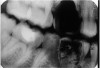
Description: Double exposures occur when the same film is used for more than one exposure (Figure 1). This can occur if the operator confuses an exposed film with an unexposed film and places the packet into the patient’s mouth as if it were unused. Double exposures can also result from activating the exposure button twice.
Differential Diagnosis: The resulting film is dark because it has technically been overexposed, resulting in confusing, overlapped anatomic images.
Consequences: Retakes are almost always necessary because of the lost detail caused by anatomic superimpositions. Fortunately, double use of a packet usually occurs with the same patient in the chair; but if a previously exposed film from one patient were placed into the mouth of another, the operator would be running the risk of cross-contamination and transmitting disease between patients.
Remedy: After a film packet has been exposed the operator should place the film into a lead receptacle. Unexposed films and exposed films should never be kept in the same area.
Clear Film
Description: Clear films are those that have not been exposed to x-rays or that have the entire emulsion cleared during processing.
Differential Diagnosis: This can occur if the x-ray unit is not switched on when the film is made, if the PID is not aligned with the XCP during exposure, if an unexposed film is processed, if the film is placed into the fixer before it goes into the developer or if the radiograph was left in the fixer too long.
Consequences: Obviously, a retake will be necessary. If the machine was not on when the exposure was presumably made, the patient will not have received radiation; however, if processing technique caused the error, the patient will be subjected to additional radiation dose.
Remedy: The operator should pay close attention to details while exposing all radiographs.
Black Film
Description: A black film is one without any detectable image; in other words, a totally dense film.
Differential Diagnosis: It would take a great amount of excess radiation exposure to render a black film and, thus, overexposure is an unlikely cause. Exposing the film to white light before processing is the most common cause. In addition, excessive development time or very high developer temperature will also produce black films.
Consequences: The cause of the error will need to be corrected and the film retaken, subjecting the patient to additional dose of radiation.
Remedy: It is the operator’s responsibility to be aware of machine settings and also the chemicals used and to refer to the replenishment chart, which should be posted outside the darkroom.
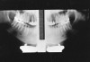
Reverse Film Placement
Description: Reverse film placement results when the beam passes through the lead foil backing before it strikes the film emulsion. The lead shield attenuates the beam by approximately 66%, resulting in a light film with a visible pattern of the embossed lead shield superimposed on the image. The pattern usually resembles a series of V-shaped herringbones or dotted “tire tread” shapes, as in the left side of Figure 2.
Differential Diagnosis: The pattern of the embossed backing differentiates reversed film from other light films.
Consequences: The image may still be acceptable, despite the error. If the pattern obliterates detail or interferes with the film’s diagnostic quality, a retake is necessary.
Remedy: The operator should be aware of the front and back of the film. Each film has an embossed dot (orientation marker) found on the front of the film. The raised surface of the dot should be closest to the PID. The back of the film has a different color and/or a flap where the operator will retrieve the exposed film prior to developing.
INCORRECT FILM PLACEMENT AND PID ERRORS
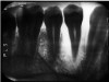
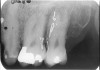
Elongation
Description: A radiograph is a two-dimensional representation of a three-dimensional object. Incorrect positioning of the tubehead’s central ray relative to the object to be radiographed results in a distorted image. If the central ray of the tubehead is placed at too shallow a vertical angle relative to the long axis of the teeth, and thus is not perpendicular to the long axis for paralleling technique or the bisector (90º angle) in the bisecting angle technique, the crown and root images will appear long (Figure 3).
Differential Diagnosis: If vertical beam angulation is too shallow, the entire tooth and roots will appear elongated. If film bending was at fault, the roots will generally be elongated, but the crown will appear normal.
Consequences: The image may still be acceptable, despite the error. If the elongation interferes with the film’s diagnostic quality, a retake is necessary.
Remedy: The operator should review technical procedures regarding vertical angulation in relation to either Paralleling or Bisecting technique, and repeat the film. The operator should increase the vertical angulation in order to correct elongation of an image.
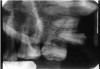
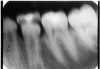
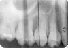
Foreshortening
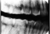
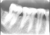
Description: Foreshortening occurs when the central ray from the tubehead is too high, making the vertical beam angulation too steep. The image appears shortened particularly at the portions of the teeth that were closest to the beam (Figure 4).
Differential Diagnosis: Visible shortening of the teeth, with somewhat wider appearance of objects closest to the x-ray head. The incisal or cuspal edge may be partially missing. The posterior teeth may show a greater distance between the buccal and lingual cusps (Figure 5).
Consequences: The image may still be acceptable, despite the error. If the foreshortening interferes with the film’s diagnostic quality, a retake is necessary.
Remedy: The operator should review technical procedures regarding vertical angulation in relation to Paralleling technique or Bisect-the-Angle technique and repeat the film. The operator should decrease the vertical angulation in order to correct foreshortening of an image.
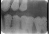
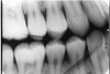
Proximal (Horizontal) Overlap
Description: To open the interproximal contacts between adjacent teeth, the horizontal angulation of the x-ray beam needs to be parallel to the teeth and film being exposed. In particular, the central ray of the x-ray beam must be at a 90º angle to the interproximal areas desired in the film. If it is not, the surfaces will overlap, causing image superimposition of adjacent teeth, which appear as teardrop shaped, light regions between the teeth on the radiograph (Figure 6).
Differential Diagnosis: The light, droplet-shaped areas between the teeth indicate proximal overlap. The central ray or beam was not parallel with the interproximal surfaces. If the overlaps are larger in the posterior half of the film, the horizontal angulation was angulated too much from the mesial toward the distal. The reverse is true for a film in which the overlaps are larger in the anterior half of the film.
Consequences: Important information about incipient interproximal caries can be obscured. The darker lines that form at the zone of changing density in overlapping areas could be misinterpreted as interproximal caries.
Remedy: The operator should review technical procedures regarding horizontal angulation and repeat the film. The operator should be directing the central beam into the interproximal spaces of the teeth needing to be radiographed.
Film Placement
If the film is placed incorrectly in the patient’s mouth, the resulting image will be either incorrect or inadequate resulting in an undiagnostic x-ray. Vertical position refers to the placement of the film in relation to the long axis of the tooth. Horizontal placement refers to the anterior-posterior position of the film. Some positioning errors are summarized below.
1. Maxillary vertical film position too high: Periapical tissues are adequately seen, but details of the tooth crowns are missing at the occlusal or incisal edge of the film.
Remedy: The operator should place the bite block of the XCP on the incisal edge to ensure that 1/8 inch of the film is beyond the incisal edge of the teeth, and then have the patient bring the mandibular teeth to the bite block.
2. Maxillary vertical film position too low: Tooth crowns are adequately seen, but the periapical areas are missing at the periapical edge of the film.
Remedy: The operator must place the film further into the mouth to avoid hitting the hard palate.
3. Mandibular vertical film position too high: Crowns are adequately seen but periapical tissues are missing at the periapical edge of the film.
Remedy: The operator should place the bite block of the XCP on the incisal edge on the mandibular teeth, making sure to avoid any tori, then the operator should have the patient bring the maxillary teeth down to the bite block.
4. Mandibular vertical film position too low: The periapical tissues are adequately seen, but the crowns are missing at occlusal edge of the film.
Remedy: The vertical angle of the XCP is not forming a correct parallel angle. The operator must ensure that the film is placed so that the incisal edge touches the bite block correctly in order to have the long axis of the tooth and the film parallel to each other. The operator may have to place the film further back in the patient’s mouth.
5. Horizontal film position incorrect: If the film is placed either too far mesial or too far distal into the oral cavity, the image will not adequately include the desired area of interest.
Remedy: The operator must place the film next to the correct teeth being radiographed.
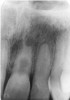
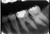
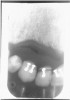
6. Vertical-Horizontal film placement errors: It is possible to misalign the film so that it is incorrect on both positions, compounding the effects of the individual positioning errors. Figure 7 is a radiograph which resulted from the film being positioned too far posteriorly in the horizontal position and too high in the vertical position. Notice that due to these placement errors, the mesial surface of the first mandibular premolar and the apices of the first and second mandibular premolars are not recorded.
Remedy: The operator must place the XCP bite block directly on the teeth being radiographed. The patient must bite hard enough to hold the XCP bite block in place. If the patient finds that the bite block and the film are uncomfortable, the operator must reposition the film, possibly tilting the film or using a different holder, however the operator must maintain the correct placement.
PID (Cone) Cutting
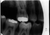
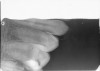
If the PID is not placed completely over the film, the collimated beam will not expose the portion of the film that was outside the edge of the PID. The unexposed area will be completely white. If the collimator was round, the border will appear curved. Figure 8 illustrates a cone cut resulting from incorrectly positioning a round collimator. If the PID has rectangular collimation, the white, unexposed area will be bordered by a straight line.
Cone cuts occur frequently during bitewing exposure. The operator fails to align the central ray with the center of the film packet due to the fact the operator tends to lose sight of the bite tab as the patient’s mouth closes. Films with cone cuts should be repeated only if the information that has been obscured is not obtainable from films of adjacent areas. Since there is usually sufficient anatomic repetition in a full mouth dental series, one cone cut does not usually require retake of a film.
Remedy: When using the PID the operator must make sure the PID and the collimator are touching and are at the correct angle. The x-ray beam must be centered on the film (or sensor) to ensure that all areas are exposed. If the operator is exposing bitewing films, he/she should ask the patient to smile in order visualize the bite tab as the patient’s mouth closes. The operator can touch the bite tab and visually mark the tab’s location by noting facial landmarks. The operator can also use their fingers as an extension of the cone to approximate PID coverage.
Note: For diagnosable radiographs every time, the film, teeth, and end of the PID should be parallel at all times. This is achieved by properly using film-holding devices such as the XCP, the disposable Stabe, or the Snap-a-Ray. The patient should never hold the film as this can increase errors and unnecessarily radiates the patient’s hand.
MOTION, FILM BENDING, AND FOG
Motion
Motion distortion can occur if the patient, tube head or film moves during the exposure. Such movement leads to blurred edges of the image detail (Figure 9). Generally, motion distortion results in unusable radiographs. These radiographs should be retaken unless the patient cannot cooperate or unless the tubehead is unstable. A machine with an unstable tubehead should be taken out of service until it is professionally repaired.
Remedy: Check the equipment on an annual basis for any tubehead drift. Make sure the patient understands they must hold completely still until the exposure is completed.
Radiolucent Bend Artifact
Also known as film creasing, this is caused by the abrupt bending of the radiographic film prior to processing, releasing enough energy to activate the silver bromide crystals on the bend line. These activated areas appear as dark lines across the processed film. In Figure 10, the dark line running across the mandibular region is a positive bend artifact. The dark lines across the lower right corner resulted from the common practice of bending the corners of the film packet to adapt it to the contour of the mouth for the patient’s comfort.
Remedy: Do not bend the corners of the film. The operator can move the film away from the teeth and still maintain the proper placement. There are products available that will cover the corners of the film in order to soften the edges.
Radiopaque Bend Artifact
A negative bend stretches and inactivates the film emulsion. This sometimes happens during film placement as the film gets bent against the roof of the patient’s mouth. A negative bend results in a light or white defect, as seen in the right-center of Figure 11.
Remedy: The operator should not have long fingernails, this presents infection control issues as well as possible artifacts while taking radiographs.
Static Electric Discharge
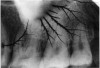
Damage from static electricity usually occurs as the film is prepared for processing. The synthetic material in some office fabrics can cause a static discharge to jump to the film, particularly when the darkroom humidity is low. Protective latex gloves can cause static electricity that produces a black, smudge-like image. Usually however, the damage is done as the film comes out of the packet and friction between sliding components generates a static charge sufficient to energize the silver bromide emulsion. The resulting artifact appears as radiolucent lines and/or areas, often with a “tree-like” configuration, as in Figure 12. Static electricity can also cause a localized overexposure.
Remedy: The operator should slowly remove the film from the film packet. The dental office also can operate a humidifier in areas where it is very dry.
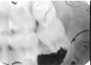
Fog
Fogging is a generalized softening and obscuring of the image that results in increased density and a decrease in film contrast. The overall appearance of the film is gray, almost like a shadow forming on amalgam restorations. Its causes include using old or expired film, storing film improperly (excessive hot or cold), chemical fumes, light or scatter radiation to unexposed film, contamination of processing solutions, using an unsafe or improper safelight conditions during processing, and allowing white light to leak into the darkroom.
Remedy: The operator has a responsibility to perform the “coin test” monthly in order to detect darkroom light leaks, check expiration dates, to store all film in a cool, dark place free from any scatter radiation and chemical fumes and also to avoid contamination of processing solutions. Do not keep films (exposed or unexposed) in an area where scatter radiation could reach them.
PROCESSING ROOM ERRORS
Light Leaks
Light leaks will cause various degrees of damage, from light fogging to completely black films, depending on the intensity of the white light exposure and the duration for which the film was exposed to white light. The most common causes of light damage are an unsafe safelight and accidentally opening the darkroom door while film processing is underway. However, ambient light can leak into the room through wall seams, doorways, keyholes and any other structural junctions.
Remedy: Darkroom integrity should be checked monthly by using the “coin test.”
Unsafe Safelight
Failed safelighting will cause the film to be fogged or completely dark, depending on the intensity and duration of exposure. Usually a filtered 10- to 15-watt bulb, placed 4 to 6 feet from the work surface, provides adequate working light for darkroom procedures. The light orange Kodak Morlite filter transmits the most light and is therefore easier to work under; however it cannot be used when processing the more light sensitive extraoral films. Extraoral films require the use of a ruby red GBX-2 filter. The safelight should be checked monthly using the coin test. With safelight on, place a coin over an unexposed film, let it lie on the darkroom table for several minutes and then process the film normally. If the film is clear, the darkroom and safelight are in operating order. If the coin casts a shadow on the film, the operator can assume that either the safelight was not really safe or that outside light leaked into the darkroom. Repeat the coin test with the safelight off. If the film is clear, then it can be assumed that the safelight is malfunctioning. If a shadow develops with the safelight off, the darkroom itself should be checked for light leaks.
Remedy: If the above test produces a negative result the operator has a responsibility to correct the error or not use the darkroom and/or daylight automatic processor until the problem is corrected.
Contamination
The darkroom work area must be kept clean, dry and dust-free. Foreign particles will adhere to the film emulsion and prevent developer and fixer solutions from contacting the underlying area. Figure 13 illustrates several examples of contamination. The small dark spots scattered across the film are dust particles; the white streak in the upper right corner represents an area where rough handling stripped the emulsion; the two large, dark areas resulted when the fluoride contacted the film surface; and the white hair-like artifact on the mandibular area is a scratch picked up in the darkroom. Contamination can also occur from immersing the film in fixer before developing, cross-mixing the developer and fixer solutions (while checking the temperature or because of incomplete rinsing between immersions), and allowing unprocessed film to contact liquid on the darkroom counter prior to processing.
Remedy: All dental team members who use the darkroom and/or daylight loader of an automatic processor must leave the area clean and free of possible contaminates.
Incomplete Submersion
Description: If a film is not completely submerged in developer solution, the area that was not in contact with the fluid will be completely clear after the film is fixed. This error most frequently occurs with the top-most film on a manual system developing rack. The operator must visually inspect the rack and developer solution level to make sure all films are completely covered.
Differential Diagnosis: A portion of the film will be completely clear. Usually, there is a rippled margin between the developed and clear areas caused by the movement of the fluid surface (Figure 14).
Consequences: Unless the diagnostic information can be obtained from other films, or unless the clear margin is sufficiently high on the film, a retake is usually necessary.
Remedy: The operator must check solution levels at least daily and replenish as needed.
Overdevelopment
Description: Overdevelopment results in a dark, dense film that is virtually identical to an overexposed film.
Differential Diagnosis: Since an overdeveloped film is so similar to overexposed films and film processed at excessive temperatures, determining the cause of a dense film is difficult. As a rule, it takes several times the manufacturer’s recommended immersion time to completely ruin a film. Therefore, the operator should first check the solution temperatures, and then consider overexposure.
Consequences: Overdeveloped films often can be used with the help of a bright light or salvaged using long-exposure duplication or reducing agents (Farmer’s Solution).
Remedy: The operator must check the temperature of the developer each time by reading the thermometer and then checking the developing chart for the correct time-temperature recommendations.
Underdevelopment
Description: Underdevelopment results in a light film that is virtually identical to an underexposed film.
Differential Diagnosis: Since an underdeveloped film is so similar to underexposed films and films processed at too low temperatures, determining the cause of a thin density film is difficult. The operator should first check the solution temperatures, and then consider underexposure and underdevelopment.
Consequences: Underdeveloped films lack detail and are generally unusable. As a rule, they cannot be salvaged using duplicative or chemical means and have to be repeated.
Remedy: The operator must check the temperature of the developer each time by reading the thermometer and then checking the developing chart for the correct time-temperature recommendations.
Developer Temperature
Description: If the developer temperature is too high, it will be overly active and cause an overdeveloped, dense film. If the temperature is too low, the film will yield a light, thin-density image.
Differential Diagnosis: Again, differentiation is difficult because temperature-related errors produce the same kind of image as time- and exposure-related errors. Temperature is easily checked and, therefore, should be the first potential error evaluated.
Consequences: Generally, the same as those for over and underdeveloped radiographic exposures.
Remedy: The operator must check the thermometer, found in the developing solution, and regulate the solution to maintain a temperature of 68º Fahrenheit.
Expired/Exhausted Developer
Description: Weak, exhausted and/or expired developer results in a light, limited-detail image.
Differential Diagnosis: Often, the processed film has a noticeable brown hue due to the oxidation of the developer’s hydroquinone component.
Consequences: Generally, the same as those for underdeveloped radiographic film.
Remedy: The operator must check the strength of the developer on a daily basis. The operator can use a tool called a dental radiographic normalizing and monitoring device. This device is designed to check the strength of the developing solutions and the correct exposure time. There are some states that require using this device as part of the office’s quality assurance program.
Air Bubbles and Film Contact
Description: Air bubbles prevent the solutions from contacting the emulsion and result in dot formation in the corresponding areas. Since most dental x-ray film is coated with emulsion on both sides, the artifact will only appear on the side on which the bubble was located.
Differential Diagnosis: If the bubble occurred as the film was immersed in the developer solution, the dots will take on a relatively radiopaque appearance. If the bubble happens during fixation, the area will not clear and the artifact will appear dark and may turn brown with time.
Consequences: The relative damage is dependent on the size, location and number of artifacts.
Remedy: The operator should remember to agitate, but not over-agitate, the film rack when immersing it in the processing solutions.
Underfixed
Description: Since fixation removes unaltered and unexposed silver halide, an underfixed film will retain some of this chemical. At first, the film appears relatively normal, but it changes with time, approximately three to six months
Differential Diagnosis: As the film ages, it turns progressively more brown and eventually becomes unreadable.
Consequences: The film may be usable at first, but deteriorates fairly rapidly and, therefore, cannot be used for future comparative evaluation. A good rule of thumb is to fix the film for at least ten minutes.
Remedy: If the doctor requests the film to be read quickly, “quick reading/3 minutes,” it is the responsibility of the assistant to return the film to the fixing solution for 7 (seven) more minutes.
Inadequately Washed
Description: If a film is inadequately washed after fixing, unaltered silver halide will remain, with the same effects as underfixing.
Differential Diagnosis: As the film ages, it turns progressively more brown and eventually becomes unreadable. The film will also have silver bromide crystals remaining on it. These crystals will appear white and almost salt-like.
Consequences: The film may be usable at first, but deteriorates fairly rapidly and, therefore, cannot be used for future comparative evaluation.
Remedy: Wash each film for at least 20 minutes.
Excessive Fixation or Washing
Description: Excessive fixation or washing clears too much and results in a light image. As with underdevelopment, the manufacturer’s recommended fixing and washing times must be greatly exceeded to produce a completely clear film. However if the operator leaves a film in the fix or water overnight the latent image will begin to wash out.
Differential Diagnosis: Differentiating may be difficult because the light image could be caused by underexposure, underdevelopment or too low solution temperature.
Consequences: Generally, the same as those for underdeveloped radiographic film. If left in the fix solutions overnight, the image may be completely gone and the radiograph will appear clear.
Remedy: The operator must be aware of the proper times necessary for fixing and washing in order to produce a diagnostic film.
Torn Emulsion
Description: The film emulsion is particularly susceptible to tearing when it is wet. Tearing most often occurs as a result of films scraping each other, the sides of the tank, other film racks or from contact with the operator’s fingernails. Contact tears will be variable in shape (Figure 15).
Differential Diagnosis: Usually tears will be irregularly shaped and light or white, with irregular margins, while droplet artifacts will be fairly rounded.
Consequences: Generally dependent on the size and location of the tear. If diffuse, the film may have to be retaken.
Remedy: The operator must not allow films or film racks to touch each other during processing. The operator must also take care when using an automatic processor not to allow the films to overlap as they enter the roller or transport system.
Reticulation
Description: Reticulation results when an excessive temperature variance between the developer and fixer solution causes the emulsion to expand and contract. Such stretching causes the emulsion to craze or split and results in a blurred, granular image. Reticulation can also be caused from powder on gloves. The more sensitive the film, the more likely this will occur (Figure 16).
Differential Diagnosis: The granulation apparent on the film is the key to detecting reticulation errors.
Consequences: Depending on the degree of damage, the film may or may not be usable.
Remedy: The operator must monitor the temperatures of the solutions and correct them whenever possible. The operator must wash hands and gloves before handling film when using powdered gloves.
Film Contact
Description: The cause of films contacting each other depends on the type of processing system used. With manual systems, contact usually occurs when multiple racks are processed at the same time and touch each other in the tanks. With automatic systems, contact errors most often happen when films are fed into the processor too closely together, and can be returned to the operator dried and adhered together. Depending on when the error occurred, portions of the films will display errors associated with underdevelopment or under fixation.
Differential Diagnosis: If contact occurred during development, the corresponding area will be partially or completely underdeveloped. If it occurred during fixation, the area will not clear and will brown and discolor. The film also may have torn emulsion as the operator separates the films for viewing.
Consequences: Depending on the degree of contact, the film may or may not retain diagnostic quality.
Remedy: If the operator finds that two or more films are stuck together after processing, the operator, in a dark place, can separate the film into pure fix for 4 minutes prior to correctly rinsing in the water bath. This process will sometimes allow the dentist to successfully view the films and therefore eliminating the need for retakes.
Contamination
Saliva contamination of the film happens when the packet is not adequately dried after removal from the patient’s mouth. The residual moisture can cause the black paper backing to adhere to the film and result in the hair-like artifact seen in the lower central portion of Figure 17.
Chemical contamination can happen if the substance is transferred from the operator’s fingertips, resulting in a fingerprint pattern on the film or if the film picks up a foreign substance during exposure or processing. Localized contamination such as that from fluoride mouthwash may lead to an artifact like that shown previously in Figure 13.
Inadequate rinsing also causes a form of chemical contamination in that the developer and fixer solutions act upon one another instead of on the film and create a shotgun effect of dark precipitated granules or white salts across the film. Automatic processor transport rollers become contaminated with use and must be cleaned by using a cleaning film regularly in order to avoid the type of artifact shown in Figure 18. These vertical streaks can be avoided by cleaning the rollers each morning before processing patient films.
Remedy: The operator must follow a well-established quality assurance program according to manufacturer’s recommendations.
Foreign Objects
If the patient wears any removable appliance, it should be removed prior to exposing any radiograph of the area. The degree to which an appliance interferes with a radiograph’s diagnostic quality depends on its type, location, composition and how much it attenuates an x-ray beam. Figure 19 is a radiograph taken with the patient’s full denture in place. Even though the porcelain teeth and metal studs appear relatively radiopaque, the radiolucent acrylic baseplate allowed full visualization of underlying tissues and, thus, the exposure did not have to be retaken.
An appliance with a radiopaque metallic baseplate would completely obscure most structures of interest and render the film useless. Therefore, it is necessary to have the patient take out any removable appliance within the intended field of examination. It should be noted that while an appliance that covers the area of interest should be removed, leaving an opposing denture in place often facilitates making the exposure and even improves diagnostic quality because the patient can more easily maintain film position.
Eyeglasses, earrings, necklaces and jewelry, and an improperly positioned film-holding device can all cause foreign object artifacts to appear in the radiograph. Always check for any facial or oral piercing that will have potential to appear on the radiograph and ask the patient to remove it.
SUMMARY: RADIOGRAPHIC FILM HANDLING AND PROCESSING ERRORS
Film Too Dense
• mA/exposure time/kVp setting too high
• source-to-object distance too short for chosen exposure parameters
• low object density (eg, young children or elderly patients with thin bones or osteoporosis)
• film speed faster than required for chosen exposure settings
• film left too long in developer solution
• developer solution too hot
Film Too Light
• mA/exposure time/kVp setting too low
• source-to-object distance too long for chosen exposure parameters
• high object density
• film speed slower than required for chosen exposure settings
• reverse film placement for exposure (eg, embossed foil shield toward the x-ray beam)
• film removed from developer solution too soon
• developer solution exhausted
• film left in fixer solution too long
Fogging
• contamination or deterioration of processing chemicals; follow manufacturer’s directions regarding replacement or replenishment of chemicals
• film expired/age fog; check expiration date before exposure
• film exposed to light, heat or scatter radiation during storage
• wrong or faded filter in safelight; safelight too close to film unwrapping area
• slight light leak in darkroom
Dark Spots or Regions
• air bubble on film surface during fixing
• film contaminated by fixer before developing
• light leakage into film packet
• inadequate fixation
• inadequate washing
• contaminated developer
• contaminated rollers in an automatic processor
• contact with chemicals (eg, fluoride, silicone)
• film bent or creased before processing
• static electric discharge
Reticulation
• temperature difference between fixer/developer/wash
• powder on gloves
Image Distortion
• magnification: decreased source (PID)-to-object (teeth) distance; increased object (teeth)-to-film distance
• elongation: vertical angulation too small; film curved horizontally; excess angulation between film and tooth without compensating by adjusting the vertical angle of the tubehead with the bisecting angle radiographic technique
• widening: film bent vertically
• foreshortening: vertical angulation too steep; insufficient angulation between film and tooth without compensating by adjusting the vertical angulation of the tubehead using the bisecting angle technique
• overlapping Interproximal Surfaces: incorrect angulation of tubehead with respect to the mid-sagittal plane (incorrect horizontal angulation)
• incorrect spatial relationship between teeth and investing bone: inherent error in the bisecting angle radiographic technique
• root apices not recorded: film placed too low in the maxilla or too high in the mandible; vertical angulation too low; film curved horizontally; cone cutting
ERRORS IN PANORAMIC DENTAL RADIOGRAPHY
Head and Film Position
The diagnostic quality of a panoramic radiograph is largely determined by the same geometric considerations that apply to conventional intraoral radiography—in essence, the relative position of the patient’s jaws, teeth, x-ray beam and film plane. Therefore, the adverse effects of malpositioning and misalignment are equally serious with panoramic dental radiographs.
Manufacturer’s directions should be followed closely as each manufacturer’s machine is slightly different. However, in general, patients should be seated or standing erect with the cervical spine as straight and as centered as possible (located in the focal trough). The patient’s mid-sagittal plane should be perpendicular to the floor and the Frankfort plane should be parallel to the floor. The patient’s teeth must be positioned within the focal trough.
Patient Positioning Errors
Some of the most common errors in panoramic radiography are listed below in descending frequency of occurrence:
• chin too low
• tongue is not raised to the roof of the mouth
• patient’s positioned is slumped
• head is tilted
• head is rotated
• lips are open
• teeth are too far forward
• bite guide is not used
• chin is high
• machine is too high
• prosthesis was left in place
• head is too far back
• chin is not fully in the rest
• patient moved during exposure
Vertical Height
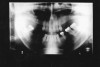
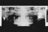
If the patient’s head is positioned too high, or if the film cassette and tubehead are too low, the superior part of the condyles of the ramus and much of the maxilla will be missing from the film, as in Figure 20. In the reverse situation, if the patient’s head is too low, or the cassette and tubehead are too high, the lower border of the mandible will be lost.
Chin/Head Position
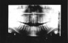
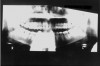
If the patient’s chin is tilted downward, the arches will appear constricted. The condyles will appear closer together and may be cut off at the top of the film. The overall appearance will be that of a “Cheshire cat grin” due to the accentuated curve of Spee (Figure 21). If the patient’s chin is tilted upward, the image of the arches will be one of overall flattening or elongation. The condyles will be farther apart and may be cut off at the sides of the film. The general appearance is that of a wide “grimace,” as in Figure 22, due to a flattened curve of Spee.
If the patient’s head is positioned too far forward, the anterior teeth will not be within the focal trough and will appear blurred. Being in a labially displaced position, they will be visualized as narrower than the actual object they depict. Conversely, if the patient’s head is too far back, the anterior teeth will not be within the focal trough and they will also appear blurred. However, being in lingual displacement, they will appear wider than the object they depict.
If the patient’s head is tilted, the image visualized will appear skewed diagonally across the film. If the head is rotated, the result will be one of image magnification in the area of the anatomy farthest from the film. The patient chin rest bite guides and calipers provided by the machine’s manufacturer enable the clinician to prevent these errors in centering the object.
Cervical Spine Slump
When the patient’s cervical spine (neck) is allowed to slump forward, instead of remaining perpendicular to the floor, it is then positioned too far anteriorly. The vertebrae are projected more visibly on the lateral borders of the film and obscure the anatomic structures of the ramus area.
Motion
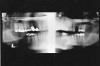
Vertical, horizontal or compound patient movements and slippage or vibration of the tubehead or film holder can produce a range of artifacts on panoramic films. With conventional films, motion produces generalized unsharpness; with panoramic films, however, motion unsharpness only affects the portion of the film that was being exposed at the time motion occurred. Therefore, depending on the extent and duration of movement, only a small, discreet portion of the exposure may be blurred while the rest of the film is within acceptable limits. Short-duration movement may be difficult to detect because the resulting artifact can look suspiciously like a pathological condition.
The top radiograph in Figure 23 is a normal panograph. The bottom panograph is one that was affected by short-duration movement. Notice how the patient’s left mandible appears to be notched along the upper margin. The notch could easily be interpreted as calcification at an old fracture site when, in reality, it is a movement artifact. Remember, when viewing radiographs, the patient’s left is on the viewer’s right.
Focal Trough
Panoramic radiographs blur out some anatomic structures in order to detail others. The U-shaped area where the maxilla and mandible are the sharpest is the image layer or focal trough. Image sharpness within the trough is determined by the position of the object in respect to the x-ray source and the film plane as it rotates around the axis or center of rotation. While different x-ray machines have different trough sizes and shapes, there are several general statements that can be made about all panoramic exams: 1) As the size of the focal trough increases, image sharpness decreases. 2) Image magnification and blurred margins increase more rapidly medially than laterally to the focal trough. 3) Trough thickness is directly related to acceptable image blurring. The thicker the trough, the more the image will be blurred.
The focal trough concept is used to prevent superimposition of extraneous structures which would impede clear view of the dental arches, and allow the clinician to view a discrete, selected image field. Unfortunately, one of the disadvantages of this concept is the exclusion of structures that may reveal diagnostically important information. For example, supernumerary teeth or other dental pathosis lying outside the focal trough may not visualize clearly enough for diagnosis.
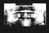
Conversely, this same panoramic quirk could suggest the presence of a condition that did not really exist. For example, if the apices of the mandibular incisors were missing, as they are in Figure 24, the clinician could suspect external resorption. In this particular case, further examination with selected periapical films confirmed that the patient had normal, pathology-free dentition. The incisal apices had not visualized on the panograph because the operator had positioned the patient slightly too far forward for the apices to fall within the focal trough.
Magnification
Some degree of magnification is unavoidable, even with perfect technique. Magnification is inherent and regionally disproportionate across the film. The image’s horizontal dimensions are determined by the speed with which the film moves; therefore the dimensions visualized do not necessarily represent the actual size of the object they depict. Additionally, the degree of magnification depends on the object-to-film distance (also known as the focal film distance) and, since every individual has somewhat different oral dimensions, they do not exactly conform to the machine’s engineered focal trough. As a result, image enlargement will vary from patient to patient. As a rule, objects displaced toward the lingual (tongue) side of the focal trough, such as when the patient is positioned too far back, will appear magnified. Objects displaced toward the labial (lip) side, such as when the patient is positioned too far forward, will appear narrowed.
Ghost and Secondary Images
The degree to which a panoramic radiograph blurs out objects outside the focal trough is somewhat dependent on how radiodense those objects are. The diffuse radiopaque shadow near the identification label on the right border of Figure 25 is actually a ghost image of the clearly outlined metallic object at the illustration’s left. The operator must assure that the patient has removed dental appliances, earrings, eyewear, facial and oral piercing jewelry and necklaces before making a panoramic exposure. Frequently the patient will be wearing a chain or necklace that cannot be seen beneath clothing.
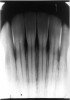
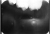
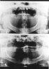
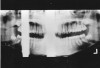
Similarly, placing the lead apron too high on the patient’s neck or bunching it at the shoulders will obstruct the beam enough to cast a ghost image of the shielding material (Figure 26). In order to equalize tissue densities, the patient’s tongue must be held against the palate. If it is not, the air space between the tongue and the palate will cast a detail-obscuring dark shadow or radiolucency at the apices of the maxillary teeth, with corresponding washed-out areas at right and left sides (Figure 27) related to the difference in density of the tongue in relation to the air space. Similarly, the patient’s lips should remain closed to equalize the densities.
Cassette and Rotational Artifacts
Panoramic radiographs involve a relatively complex series of coordinated, simultaneous movements. The film and x-ray source move in opposite directions around a central axis and in some machines the film cassette rotates on its own axis behind a narrow slit opening in the scatter guard. Because of this motion, mechanical errors can affect the quality of the exposures. If the source and receptor fail to rotate, only one portion of the jaw will be imaged instead of the entire jaw being recorded across the film. If the film fails to rotate behind the slit opening, only one very narrow band of exposed area will appear on an otherwise clear film. If the film is improperly mounted in the film holder, a partial image will result, but the majority of the processed film will be clear. In addition, the x-ray source must continue to generate a beam throughout the examination or clear zones will develop over the portion of the film that was passing behind the slit opening at the time the exposure was interrupted (Figure 28).
Other Errors
The exposure, handling and processing errors described for intraoral films also apply to panoramic radiographs. Particularly noteworthy is the sensitivity of panoramic or any screen film to static electricity artifacts. It is also extremely important to follow the manufacturer’s recommendations in all areas while exposing a panoramic radiograph.
SUMMARY: PANORAMIC FILM HANDLING AND PROCESSING ERRORS
Patient’s Head Positioned Too Far Forward
• image of cervical vertebrae seen bilaterally distal to, or slightly overlapping upon, the ascending ramus
• premolar proximal overlap increased
• increased magnification in the posterior
• dental structures may be excluded from the focal trough
• anterior teeth appear narrower than actual size
Patient’s Head Positioned Too Far Back
• posterior detail such as the condyle may be omitted
• dental structures may be excluded from the focal trough
• increased magnification in the anterior
Patient’s Head Positioned Too Low
• lower border of the mandible excluded
• orbits often seen in their entirety
Patient’s Head Positioned Too High
• part of the upper arch, mandibular condyle, and coronoid processes may be excluded from the film
• mandibular image relatively too high on the film
Patient’s Chin Tilted Upward
• flattening of the arches, backward displacement of the rami and exclusion of the condyle from the image at the sides of the film
• curve of Spee is reversed, appears as a wide grimace
• hard palate superimposed over apices of maxillary teeth
Patient’s Chin Tilted Downward
• occlusal plane too high in the posterior segment of the film
• inwardly tipped condyles are closer together
• apparent widening of mandibular symphysis
• possible superimposition of the hyoid bone on mandible
• curve of Spee constricted, appears as a “Cheshire cat grin”
• possible exclusion of condyles at the top of the film
Image Distortion
• magnification: decreased source-to-object distance; increased object-to-film distance; objects displaced lingually to the focal trough
• narrowed image: objects displaced labially to the focal trough
• incomplete image - narrow, radiolucent vertical area on an otherwise clear film usually: due to failure of the apparatus to rotate axially; partial image on clear film usually due to improper positioning in the film holder; clear areas in an otherwise normal panoramic film usually due to interruption of the exposure during axial rotation
• overlapping occlusal surfaces: teeth were not separated by a bite-block or cotton roll during exposure
• maxillary radiolucency: tongue not held against palate, leading to uneven tissue density and air space visualization
• ghost images: jewelry or radiopaque dental appliance cross-visualized; lead apron too high on patient’s neck or bunched on shoulders; patient’s neck slumped forward causing imaging of cervical vertebrae
DIGITAL IMAGING
Digital imaging is common practice in the world of dentistry. This technology uses electronic sensors to record images and then sends them to a computer for viewing and archiving. The images can be viewed within seconds with options to darken, lighten, and even emboss the images for diagnostic purposes. Sensors must be cared for according to manufacturer’s instruction to prolong their life and their ability to obtain diagnostic imagery.
Indirect Digital Radiography
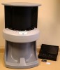
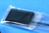
The indirect digital radiography system uses a flexible sensor that is not attached to a wire (Figure 29). The sensors come in a variety of sizes that will adapt to the patient’s mouth, allowing the operator more ease in achieving correct placement. Indirect digital radiography allows the operator to use the existing radiography equipment by simply lowering the exposure time. Once the sensor is exposed, the operator places the sensor into a processing drum (Figure 30) that uses a laser beam with electronic data to send the images onto a computer. The sensor is similar to the radiograph films and the placement and exposure errors previously discussed apply to the digital sensor.
This system allows the office to do away with the messy darkroom or automatic processor. Once the images are recorded into the computer, the sensors are recharged and can be reused. One disadvantage to this system is that the operator has a small window of time in which to place the sensors into the processing drum. If the operator takes too much time the sensor is exposed to excessive amounts of white light and the image will become lighter. White light is what clears the image from the sensors and recharges them for continued use.
Direct Digital Radiography
The direct digital radiography system uses a charge-coupled device (CCD), or sensor, that is placed into the patient’s mouth (Figure 31 and Figure 32). This sensor can be directly connected to the computer system and applicable software by a lead wire, or have wireless capabilities using radio frequency transmission to instantly transmit the image to the computer.
These direct sensors have one drawback; the sensors being used are larger, rigid and thicker in comparison to the previously discussed films. This extra bulk, and that of the plastic intraoral barrier, is often uncomfortable for the patient. The lack of sensor flexibility causes difficulty for the operator in achieving correct sensor placement. Film placement rules must be strictly observed and all teeth must be included in a prescribed film.
The sensors also are very fragile, which may cause a problem if dropped or abused in any way. Unfortunately the cost to replace one sensor can be as much as $5,499–$6,499.
Optically Scanned Digital Radiography
The optically scanned system uses regular dental films with the traditional radiography techniques. Developing takes place in specialized daylight loader machines by scanning the dried films. A digital image is then produced. This system takes additional time, requires more equipment (the optical scanning unit) and does not eliminate old equipment.
Advantages of Digital Radiography
There are several advantages to the digital radiography systems: 1) reduction in radiation dose to the patient; 2) an image can be adjusted and a clearer picture can be produced in order to identify areas of concern; 3) radiographs are stored in the computer allowing the office to go “paperless”; 4) there is no need for darkroom chemicals, providing an environmentally safe office; 5) professional case presentation for positive patient education and informed consent.
QUALITY ASSURANCE PROGRAM
Dental offices need to consider establishing a quality assurance (QA) program for dental radiographs. The step is now required in many states. A QA program will provide a mechanism to monitor x-ray machines, darkroom equipment and radiographic techniques for all operators. QA is a plan of action steps to follow that ensures that the facility will produce consistently high quality, diagnostic films with minimum exposure to patients and the dental team.
As the operator reviews the errors included in this course it may be noted that several, if not all, of the errors could be avoided if a QA program was implemented. The operator should establish a program to include the following areas:
• maintaining proper film exposing and processing techniques
• maintaining proper radiographic equipment through periodic testing
• properly posting current exposure, developing and technique charts
• maintaining and testing processing chemicals and safelighting
• maintaining proper cleanliness of both the darkroom and the automatic processor
• maintaining proper storage and handling of all films, cassettes, screens and chemicals
• maintaining proper infectious control protocols
• maintaining and recording proper compliance regarding environmental concerns: 1) properly recycling developer/fixer solutions; 2) properly recycling lead foil from film packets
To receive free additional information regarding quality control in dental radiography, a Kodak representative can be reached at 800-933-8031 (in the USA and Canada), or a free pamphlet is available via the internet at: http://www.kodak.com.
SUMMARY
Diagnostic radiographs and proper techniques benefit all patients and their overall dental care. Film can be undiagnostic as a result from various operator errors, or processing errors. A poor, undiagnostic radiograph is worse than no radiograph at all. It results in film retakes, which requires additional radiation exposure to the patient. Only through proper education, and the ability to troubleshoot and correct errors, can an licensed dental team member provide consistently diagnostic radiographs.
ABOUT THE AUTHORS
Wilhemina Leeuw, MS, CDA
Clinical Assistant Professor of Dental Education at Indiana University Purdue University, Fort Wayne. A DANB Certified Dental Assistant since 1985, she worked in private practice more than 12 years before beginning her teaching career in the Dental Assisting Program at IPFW. She is also the Education Coordinator for the American Dental Assistants Association.
Allan G. Farman, BDS, EdS, MBA, PhD
Diplomate, American Board of Oral and Maxillofacial Radiology; Professor of Oral and Maxillofacial Radiology, Department of Primary Patient Care, University of Louisville School of Dentistry, Louisville, Kentucky
REFERENCES
1. Bird D, Robinson D. Modern Dental Assisting. 10th ed. Elsevier Saunders; 2012.
2. Eastman Kodak, Successful Intraoral Radiography. Kodak Dental Radiography Series. 2002.
3. Frommer HH. Radiology for Dental Auxiliaries. Mosby; 1996.
4. Frommer HH, Stabulas-Savage J. Radiology for the Dental Professional. Elsevier Mosby; 2005.
5. Haring J, Jansen-Howerton L. Dental Radiography; Principles and Techniques. WB Saunders; 2005.
6. Langland OE, Langlais RP, Preece J. Prinicples of Dental Imaging. Lippincott, Williams & Wilkins; 2002.
7. Phinney DJ, Halstead JH. Delmar’s Dental Assisting, A Comprehensive Approach. Cengage Learning; 2003.
8. Pricing. DentiMax. Stand Alone Sensors. http://www.dentimax.com/digital-xray/sensor-pricing.html. Accessed October 31, 2012.
9. Quality Assurance in Dental Radiography; Dental radiography series. Eastman Kodak. 2007. Carestream Dental. http://gar.carestreamdental.com/~/media/Files/GAR/N-416_Quality_Assurance_Brochure.ashx. Accessed October 31, 2012.