You must be signed in to read the rest of this article.
Registration on CDEWorld is free. Sign up today!
Forgot your password? Click Here!
The dental equipment market has been growing exponentially, with some experts estimating that it will reach more than $7 billion by 2017.1 Many dentists are more likely to invest in new technology if it means they can provide both a better quality of care and greater financial returns for their practices. In addition, many patients may be lured to practices that have made heavy investments in technology. With greater numbers of dentists purchasing advanced technologies, the costs have decreased, making such equipment more attainable.
Cone-beam computer technology, or CBCT, is one such technology that has helped revolutionize dental care. In addition to CBCT being used for treatment planning and diagnosis in implant dentistry, the technology is now helpful for oral surgery, endodontics, and orthodontics.2-8
What Is Cone-Beam Technology?
Unlike medical computed tomography scans, which often use a fan beam to capture images, CBCT technology employs a focused beam. Compared with a fan beam, the cone beam delivers significantly lower radiation levels to the patient.9
CBCT in dentistry works by using a rotating scanner that collects almost 600 unique images for one case. During the procedure, the target is centered in the cone beam’s field of view (FOV). One 200° rotation over the area creates a volumetric data set. Then the scanning software collects and reconstructs the data into a format that can be manipulated and visualized by the practitioner.
This voxel representation is isotropic, meaning it has a physical property that has the same value when measured in different directions. The composite of software-reconstructed data can give the user the ability to view the scanned area in a 360° three-dimensional (3D) rotation.10 The corresponding slicing will provide axial, sagittal, and coronal images that can be modified, creating reconstructed panoramic and curved images. These can be zoomed further to aid in diagnosis and treatment planning.
Newer dental cone-beam units that provided scans of the entire skull became available. Many clinicians found the lower radiation levels to be more acceptable and embraced the ability to make digital surgical guides simultaneously using the scan and an impression.11,12 In the author’s opinion, the surgical guides not only removed the unknown, but it also simplified the process and made the experience level of the implantologist less important. However, these newer units were expensive and having one in a private dental practice was not feasible for many solo practitioners.
A few years later, the amount of implant cases was building in the author’s practice. The prices of CBCT machines had decreased substantially, and the ability to have smaller FOV intrigued the author. Instead of taking an entire scan of the patient from the orbital floor to the base of the mandible, it was now possible to take a small 3D image encompassing just one quadrant. Their capabilities had also expanded. Instead of this machine being a dental implant aid, it was now becoming useful for endodontic procedures. The ability to stitch multiple quadrants into one arch was also available to complete the larger implant cases.
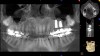
As often happens in technology, just a few years later many new CBCT units were on the market giving multiple FOVs. Dentists now had the ability to take quadrant, full-arch, maxillary sinus, full cranial, and temporomandibular joint (TMJ) scans in addition to panoramic X-rays. The number of applications for CBCT was increasing. Implant, TMJ, orthodontic, periodontic, endodontic, and oral surgery procedures that required a 3D treatment plan could now be assessed using just one machine with multiple FOVs.3 What follows here is a review of a selection of such applications.
In the field of dental implantology, CBCT is used to identify the location of anatomic structures, ie, the mandibular canal, submandibular fossa, incisive canal, maxillary sinus, and lingual nerve. It is also used to assess the size and shape of the ridge, as well as the quantity and quality of bone to determine the need for a bone graft or sinus lift. When treatment planning, it can help in the determination of the number and orientation of implants, and surgical guides can be prepared with the use of implant-planning software.7,11,12
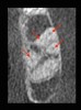
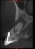
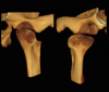
Endodontically, finding multiple canals (Figure 1), fractures (Figure 2), and pathology is now possible without physically intervening.3 Oral and maxillofacial surgeons can take advantage of CBCT to visualize the relationship of third-molar roots to the mandibular canal, as well as the location of foreign objects. Impacted wisdom teeth can be assessed, and their areas of access can be determined (Figure 3). The cephalometric capacities allow for the evaluation of facial fractures and asymmetry as well as orthognathic surgical planning.3
CBCT also has clear applications in oral and maxillofacial pathology. The 3D FOV allows for the location and characterization of lesions in the jaws, as well as their proximity to teeth and other structures. Importantly, CBCT can demonstrate the effect of a lesion in terms of expansion, cortical erosion, and bilateral symmetry that would be unavailable through conventional 2D radiography. 3
Occlusal applications exist as well. CBCT can be useful in identifying occlusal disease and joint pathologies. It can be used to better visualize the osseous structures of TMJ (Figure 4) and to depict the relationship of condyle and glenoid fossa in 3D so that the appropriate treatment can be planned and rendered.3
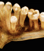
In orthodontics, CBCT is used for treatment planning for complex cases when 3D information is needed to supplement (or substitute for) other imaging. In particular, it can aid in the identification and location of supernumerary teeth and/or impacted teeth, as well as the visualization of root angulations and resorption. It is also helpful in treatment planning for patients with cleft palate. While the routine use of CBCT for orthodontics in children is controversial,6 the author has found that the use of CBCT in adults is a tremendous adjunct to the more difficult cases such as impacted anterior teeth (Figure 5).
Instead of being a financial burden, CBCT has quickly become an asset in the author’s practice. Indeed, 3D technology has made reviewing treatment plans with patients much easier. The reconstruction of the arches gives patients the ability to visualize pathology and be more willing to accept treatment plans. With the capacity to render a 3D reconstruction of the mouth and the ability to see voids caused by infection, the author has seen an increase in case-acceptance rates.
Case No. 1
A 37-year-old woman presented to the dental office with pain and swelling in the upper left quadrant. Her medical history was noncontributory. Upon examination, a periapical X-ray was taken, and a radiolucency was discovered at the apex of tooth No. 13 (Figure 6). The periapical X-ray was not enough to show the extent of the lesion and the patency of the sinus cavity.
A CBCT scan was performed, and the findings revealed a lesion extending into the sinus cavity (Figure 7). The entire left maxillary sinus cavity was completely flooded with the lesion extending to the ostium, preventing proper drainage.
Immediate extraction of the premolar was performed, and the sinus was drained through the extraction site and allowed to heal.13
Six weeks later the patient returned for a new CBCT scan. The findings showed a clean and healthy sinus cavity (Figure 8). Two implants were planned as well as a sinus augmentation.14-16
The augmentation was accessed through a crestal approach in both site Nos. 13 and 14 using a crestal approach kit (Integrated Dental Systems, www.megagenids.com). The sinus express bur was set using a built-in stopper 1 mm past the radiographic sinus floor. After the use of several hand instruments, the Schneiderian membrane was lifted, and an intact sinus membrane was observed. The osteotomies were connected through the sinus floor (Figure 9). The bone graft was placed into the sinus cavity and two implants (Integrated Dental Systems) were placed and buried (Figure 10). Four months later the implants were second-staged and the soft tissue was apically repositioned (Figure 11). The final impression was taken 2 weeks later and 10 days after that, the final crown was delivered (Figure 12).
In this case using conventional 2D X-rays would not be helpful in proper treatment planning. Had the connection with the sinus not been identified, elevation of the sinus could have led to a persistent sinus infection and a failure of the grafting procedure.13,17,18 In addition, the use of the CBCT aided the dental team in determining the width of the maxillary ridge and its depth to the sinus membrane.
Case No. 2
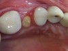
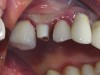
A 67-year-old woman presented to the practice with a fractured upper-left premolar. She revealed a medical history of high cholesterol, which was being controlled with Lipitor®. The patient desired a speedy solution as her employer was sending her out of the country for an undetermined period. The author had just 3 months during the patient’s summer break to complete the procedure.
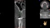
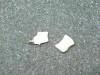
A CBCT scan was taken as well as a full-mouth impression with bite registration. The models were scanned, and an .STL file was created. The CBCT scans and .STL files were merged, and a 3D workup using advanced treatment planning software was employed (Figure 13). The software was used to design a surgical guide, final zirconia abutment, and crown. The abutment and crown were milled and sent to the dental office for use (Figure 14).
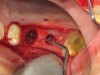
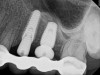
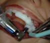
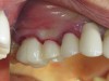
After anesthetizing the patient, the tooth was atraumatically extracted. The toothborne surgical guide was placed, and the osteotomy was prepared (Figure 15). A 4-mm x 10-mm implant (Integrated Dental Systems) was placed through the surgical guide at 45 Ncm of torque. Osstell (Osstell, www.osstell.com) readings were taken and recorded (Figure 16 and Figure 17). Due to the high-insertion torque and ISQ reading, the dental team was able to load the implant with the final abutment and crown (Figure 18 and Figure 19). The patient was recalled at 1 week, 1 month, and 3 months. The final x-ray (Figure 20) at 3 months showed excellent healing, and the patient returned to her employment.
The use of the surgical guide and other technologies allowed the dental team to deliver the final restoration at the time of the surgical procedure with great confidence and accuracy.
Conclusion
Technology is advancing at an once-unimaginable pace. Clinicians need to stay abreast of the latest techniques and know what equipment is available in order to provide optimal services to patients. CBCT technology is one of the greatest assets to dental clinicians, enabling them to look deep inside the otherwise hidden areas to diagnose and treat conditions with incredible accuracy. Costs of these machines continue to decrease, and a preowned market has emerged. The question is no longer how a practice can afford a CBCT system but rather how can it not.
About the Author
Dr. Tawil received his Doctor of Dental Surgery degree from New York University College of Dental Surgery and has a Masters degree in biology. He also has a Bachelor’s degree in psychology. Dr. Tawil received his fellowship with the International Congress of Oral Implantology, and the Advanced Dental Implant Academy and recognition for Outstanding Achievement in dental implants from the Advanced Dental Implant Academy. He has also received an advanced periodontal training certificate from Harvard School of Dental Medicine, as well as the President’s Service Award for his volunteer work in places such as Honduras, Tijuana, and Peru, where he volunteered his time along with several other dentists to provide dental care and implants to underprivileged recipients. Dr. Tawil is a member of the American Academy of Implant Dentistry, Academy of Osseointegration, American Dental Association, and the New York State Dental Association.
References
1. Dental Equipment Market (Dental Radiology, CAD/CAM, Dental Chairs, Dental Lasers) Current Trends, Opportunities—Global Forecast to 2019 August 2014. Available at: marketsandmarkets.com.com. Accessed September 13, 2015.
2. Levin RP, Judy KWM. Trends in implant dentistry. Dental Economics. http://www.dentaleconomics.com/articles/print/volume-100/issue-12/features/trends-in-implant-dentistry.html. Accessed September 13, 2015.
3. Scarfe WC, Farman AG, Sukovic P. Clinical applications of cone-beam computed tomography in dental practice. J Can Dent Assoc. 2006;72(1):75-80.
4. Orth RC, Wallace MJ, Kuo MD. Technology Assessment Committee of the Society of Interventional Radiology. C-arm cone-beam CT: general principles and technical considerations for use in interventional radiology. J Vasc Interv Radiol. 2008;19(6):814-820.
5. Wallace MJ, Kuo MD, Glaiberman C, et al. Technology Assessment Committee of the Society of Interventional Radiology. Three-dimensional C-arm cone-beam CT: applications in the interventional suite. J Vasc Interv Radiol. 2009;19(6):799-813.
6. Mah JK, Huang JC, Choo H. Practical applications of cone-beam computed tomography in orthodontics. J Am Dent Assoc. 2010;141(Suppl 3):7S-13S.
7. Ganz SD. Conventional CT and cone beam CT for improved dental diagnostics and implant planning. Dent Implantol Update. 2005;16(12):89-95.
8. Vannier MW. Craniofacial computed tomography scanning: technology, applications and future trends. Orthod Craniofac Res. 2003;6(Suppl 1):23-30;discussion 179-182.
9. Gupta R, Cheung AC, Bartling SH, et al. Flat-panel volume CT: fundamental principles, technology, and applications. Radiographics. 2008;28(7):2009-2022.
10. Gupta R, Grasruck M, Suess C, et al. Ultra-high resolution flat-panel volume CT: fundamental principles, design architecture, and system characterization. Eur Radiol. 2006;16(6):1191-1205.
11. D’Souza KM, Aras MA. Types of implant surgical guides in dentistry: a review. J Oral Implantol. 2012;38(5):643-652.
12. Ramasamy M, Giri, Raja R, Subramonian, Karthik, Narendrakumar R. Implant surgical guides: from the past to the present. J Pharm Bioallied Sci. 2013;5(Suppl 1):S98-S102.
13. Alkan A, Celebi N, Bas B. Acute maxillary sinusitis associated with internal sinus lifting: report of a case. Eur J Dent. 2008;2(1):69-72.
14. Tatum H. Maxillary and sinus implant reconstructions. Dent Clin North Am. 1986;30:207-229.
15. Boyne PJ, James RA. Grafting of the maxillary sinus with autogenous marrow and bone. J Oral Surg. 1980;38(8):613-616.
16. Misch CE. Maxillary sinus augmentation for endosteal implants: organized alternative treatment plans. Int J Oral Implant. 1987;4(2):49-58.
17. Katranji A, Fotek P, Wang HL. Sinus augmentation complications: etiology and treatment. Implant Dent. 2008;17(3):339-349.
18. Schwartz-Arad D, Herzberg R, Doley E. The prevalence of surgical complications of the sinus graft procedure and their impact on implant survival. J Periodontol. 2004;75(4):511-516.